FURNACE HEATING CHAMBER
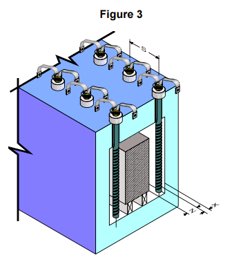
The furnace heated chamber dimension, which the SIC spans, can be the same as the hot zone length of the Sic elements as shown by the SIC under the load in Figure 3. Alternately the furnace heating chamber dimension, which the SIC spans, can be 25mm less than the effective heating length of the SIC. In this case there must be a 45 conical recess in the furnace wall as shown in Figure 3 for the SIC above the load. Recommended terminal hole diameters for various refractory walls and SIC sizes are shown in Table B. SIC should not be placed closer than two SIC diameters to each other or one and one half SIC diameters to a wall or other reflecting body. If the SIC is not able to dissipate heat energy equally in all directions, it may cause local overheating and possible failure
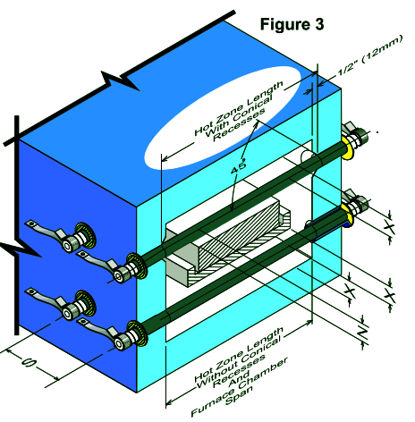
Recommended Sic heating elements Spacing
X = 2 × Sic element diameter is the Minimum,
1.5 × Sic element diameter is the absolute Minimum and requires a reduced Sic heating element Surface Watt Loading
Z = S ÷ 1.41 Minimum for Stationary Loads
Z = S ÷ 1.73 Minimum for Moving Loads
S = 2 × Sic element diameter Minimum
X - is the distance from the centerline of the Starbar to any other reflecting surface, such as a refractory wall or product
Z - is the distance from the centerline of the Sic heating element to a moving or stationary load S - is the distance from the centerline of the Sic heating element to the centerline of an adjacent Sic heating element.
Table B | |||||||||||
Minimum Hole Diameter Based on Refractory Wall Thickness | |||||||||||
Nominal QS Dia. | 100 | 150 | 200 | 300 | 400 | 3 | 5 | 6.5 | 9 | 13.5 | |
mm | Inch | mm | mm | mm | mm | mm | Inch | Inch | Inch | Inch | Inch |
10 | 3/8 | 15 | 15 | 16 |
|
| 9/16 | 9/16 | 5/8 |
|
|
11 | 7/16 | 16 | 17 | 18 | 20 |
| 5/8 | 11/16 | 11/16 | 3/4 |
|
13 | 1/2 | 18 | 19 | 20 | 22 | N/A | 11/16 | 3/4 | 3/4 | 13/16 | N/A |
16 | 5/8 | 21 | 22 | 23 | 25 | N/A | 13/16 | 7/8 | 7/8 | 15/16 | N/A |
19 | 3/4 | 25 | 25 | 26 | 28 | N/A | 15/16 | 1 | 1 | 1-1/16 | N/A |
25 | 1 | 31 | 32 | 33 | 35 | 37 | 1-3/16 | 1-3/16 | 1-1/4 | 1-1/4 | 1-7/16 |
32 | 1-1/4 | 38 | 38 | 40 | 42 | 44 | 1-1/2 | 1-1/2 | 1-9/16 | 1-9/16 | 1-11/16 |
35 | 1-3/8 | 41 | 42 | 43 | 45 | 47 | 1-5/8 | 1-5/8 | 1-11/16 | 1-11/16 | 1-11/16 |
38 | 1-1/2 | 44 | 44 | 46 | 48 | 50 | 1-3/4 | 1-3/4 | 1-13/16 | 1-7/8 | 1-15/16 |
44 | 1-3/4 | 51 | 52 | 53 | 55 | 57 | 2 | 2-1/16 | 2-1/16 | 2-1/8 | 2-3/16 |
54 | 2-1/8 | 61 | 62 | 63 | 65 | 67 | 2-3/8 | 2-7/16 | 2-7/16 | 2-1/2 | 2-9/16 |
70 | 2-3/4 | 79 | 79 | 79 | 81 | 83 | 3-1/8 | 3-1/8 | 3-1/8 | 3-3/16 | 3-1/4 |
MOUNTING
There are no restrictions on the mounting positions of SIC, although horizontal and vertical orientation are the more common. Extreme caution should be used when mounting to ensure that the SIC are not placed in tension. There should be adequate freedom to allow for the furnace and SIC to expand and contract independently. When mounting SIC vertically, they must be supported on the lower end by electrically insulated supports, or from above using support pins on an isolating plate of sufficient strength to support the weight of the elements. The SIC ends should extend beyond the furnace cold face by a minimum distance of 3 to 4 inches or 3 × the element diameter (whichever is greater). When using sealed terminal boxes, extend the cold ends by a minimum of 4-5 × the element diameter. Starbars should have their heating sections centered in the furnace chamber so that no portion of the heating section extends into the furnace wall. A conical or truncated cone shaped recess 1/2 inch (13mm) deep is sometimes located on each interior wall where the Starbar passes through. This allows the hot zone to radiate properly and helps maintain a uniform temperature in the kiln.
DH&DL SIC element installation Although silicon carbide is rigid and self support- ing, it has a fairly low impact strength, and care must be taken when unpacking and handling the elements so that they are not subjected to mechani- cal shock. Elements should always be supported in two hands.
It is important to ensure that the elements are not restricted in any way and are free to move radially, as well as axially, in their support holes. Element holes must be in line, and the whole alignment should be checked by passing a straight bar, of the same diameter as the support holes, right through the furnace, before fitting the elements
Under no circumstances should the element hot zones be allowed to enter the element support holes as this will lead to localized overheating and premature failure
Special lead-in sleeves are available for mounting all diameters of QS SIC elements and these are detailed and in the accessories size list. Sleeves should be fit from the outside of the furnace, in holes bored to a diameter that will ensure a loose fit, and the sleeves should never be cemented into position. In general, the sleeves will be far shorter than the thickness of the furnace insulation, but the clearance holes should be drilled right through to the hot face, as shown in the follow to prevent any contact between the elements and the lining, as this can lead to adhesion, and premature failure. If sleeves are not to be used, for example in brick- lined furnaces, then the elements may be fit through holes about 4 – 5 mm (1/6 –1/5 in) larger than the element diameter for element sizes up to 20 mm (3/4 in), and about 8 –10 mm (1/3 in) larger for elements from 25 – 55 mm (1 – 2 1/8 in) diameter.
Even larger holes may be required where there is a possibility of volatiles condensing in the element holes or on to the cold ends, or where the furnace lining is exceptionally thick.
Elements should always be centralized by support- ing each cold end on a small pad of ceramic mate- rial, to prevent contact between the element cold ends, and the lead-in holes. Under no circumstances should the cold ends be wrapped with ceramic fiber or other insulation, as this will lead to restriction and possible premature failure. To prevent radiation on to the terminal connections and minimize heat losses, a flexible ceramic fiber washer may be fit over each terminal end and positioned so that it rests against the outer face of the furnace
In all cases, the element ends should extend beyond the sleeve flange, or the outer face of the fiber washer, by a distance of approximately 2 – 3 times the element diameter
The use of aluminum braid is recommended for making terminal connections as it does not suffer from progressive oxidation and is sufficiently flat and soft to allow a good connection to be made. Braids are normally attached using type H spring clips, which are easy to install and require no tools. Where space is restricted, type C clips may be used, and these require a special tool for installation.
Both H and C clips rely on spring steel to maintain a good contact, and must be maintained at a tem- perature below about 250°C . For higher temperatures, types G and D clamps may be used. These are clamped to the elements using stainless steel set screws, and high temperature lubricant should be applied to the threads before installation, to prevent seizing, and later difficulty in tightening and removal. Screws should be retightened after 24 hours use.
Element connections must be kept reasonably cool and any terminal guards fit should be well venti- lated. Where sealed terminal boxes are essential, for example in controlled atmosphere furnaces, then the following procedures should be followed:
•Increase the free length of cold end outside the furnace to 4 – 5 times the element diameter
•Ensure that the surface area of the terminal covers is sufficient to ensure adequate cooling.
It may be necessary to provide finned covers to increase the surface area
•Use type D terminal clamps, and larger section connecting braids than normal
•Introduce a proportion of the process gas via the terminal boxes, to assist in cooling
•In very severe cases, some kind of forced cooling may be required
Where QS SIC elements are to be mounted vertically, a support of electrically insu- lating, heat-resistant material should be provided below the terminal end. Alternatively, elements of 16 mm diameter and above may be supplied to special order with support slots and washers to allow them to be suspended from the
top of the furnace,
x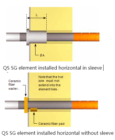
RECOMMENDATIONS FOR CHANGING RR or SE ELEMENTS
1.With the furnace in operation, determine which elements require replacement. This may be accomplished through, visual inspection or by checking the current draw of each element with a clamp-on ammeter.
2.Turn off the electrical power and lock out the electrical disconnect.
3.Remove the clamps and the straps from the ends of those elements which require replacement.
4.Inspect the clamps to be sure that they hold the straps tightly to the element. If the clamp has lost its tension, it should be replaced.
5.Inspect the strap for fraying and oxidation. If the strap is frayed or has an oxidized powder on it, replace it.
6. Remove the two halves of the failed element if broken.
7. Inspect the refractory hole to insure there is no build up or deposition in the opening. If deposits exist, ream the hole or remove them. The hole should be larger than the element diameter (See table B on page 7 of our RR brochure).
8. If element guide sleeves are used, check them for cracks or build-up of condensation residue that could cause elements to be glued into position. Replace the sleeve if damage or condensation has occurred.
9. Check the alignment and straightness of the holes through the refractory. Any binding of the element can cause element breakage during heat up.
10. Slide the new element into the hot furnace quickly enough, so the aluminum at the end is not melted off but not so fast as to cause thermal shock. Avoid hitting the opposite wall with the element. Sometimes an alloy pipe can be used to guide the new element through the heating chamber. The element outside diameter fits inside the alloy pipe inside diameter in this process. Do not force the element into the terminal holes or exert any stress on the element during installation. Page 1
11. Center the element in the furnace chamber by insuring the same amount of element protrudes from each side of the furnace.
12. Lightly pack the open space around the element with bulk ceramic fiber. The bulk fiber should only be packed one half to one inch in from the cold face. After packing, the element should be easily rotated and must be free to expand upon heating. Never cement elements in place. Alternatively, use donut shaped washers made from ceramic fiber felt/blanket, with the ID of the washer made to the same diameter as the element. There is enough “give” in the fiber felt/blanket o be able to work the washers along the terminals for a snug fit. Carefully slide the fiber washers over the ends of the elements, and push up against the furnace casing.
13. Also pack the element inside diameter with bulk ceramic fiber to a depth of one inch, if this has not been done by I Squared R. This will reduce the temperature the straps and clamps will see.
14. Reconnect the straps and install the clamps on the aluminized ends of the element. Be sure the clamps and straps fit tightly to the radius of the element making a good electrical connection. Be sure there is slack in the straps, since the elements will expand and grow in length due to heating.
15. Insure that there is clearance between the clamps and the furnace shell to prevent electrical short circuiting here.
16. Remove the electrical lock and turn the power back on. Visually inspect the elements for proper operation or check the elements for appropriate current draw using a clamp on ammeter.
17. Check the terminal connections to insure no arcing is evident.
18.Turn off the electrical power and lock out the electrical disconnect.
19.Carefully reinstall all guards or shields without hitting the elements
20.Remove the electrical lock and turn the power back on again.
21. Be sure to reset the rotary tap switches to the lowest setting after changing all elements in a furnace zone. This may not be possible if only one or two elements are changed. If rotary tap switches are not available, insure that the elements are operating on the lowest transformer tap to prevent element overloading and premature aging while still being able to maintain the furnace control temperature
RECOMMENDED SE STARBAR SPACING
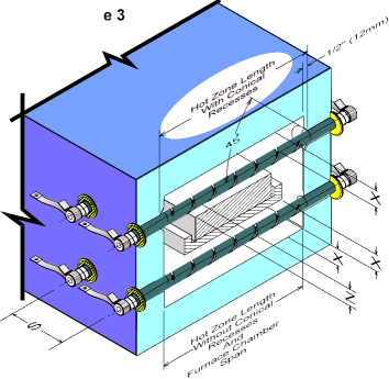
X - Distance from the centerline of Starbar to any reflecting surface, such as a refractory wall or produc
Z - Distance from the centerline of the Starbar to a moving or stationary load
S - Distance from centerline of the Starbar to the centerline of an adjacent Starbar
X = 2 x Starbar diameter is the minimum,
1.5 x Starbar diameter is the absolute minimum and requires a reduced Starbar surface watt loading
Z = S/1.41 minimum for stationary loads
Z = S/1.73 minimum for moving loads
S = 2 x Starbar diameters minimum
Installation methods QS SG element installation Although silicon carbide is rigid and self support- ing, it has a fairly low impact strength, and care must be taken when unpacking and handling the elements so that they are not subjected to mechani- cal shock. Elements should always be supported in both hands.
x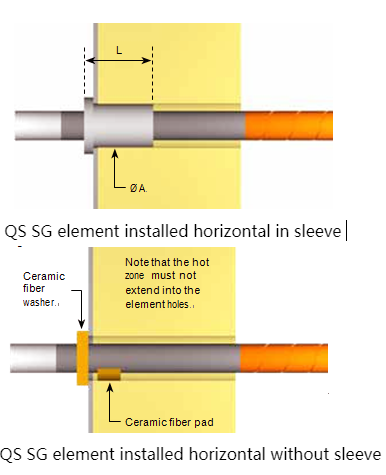
It is important to ensure that the elements are not restricted in any way and are free to move radially, as well as axially, in their support holes. Element holes must be in line, and the hole alignment should be checked by passing a straight bar, of the same diameter as the support holes, right through the furnace, before fitting the elements.
Under no circumstances should the element hot zone be allowed to enter the element support holes as this will lead to localised overheating and premature failure.
Special lead-in sleeves are available for installing all diameters of QS SG and SR elements and these are detailed iand in the Accessories size list. Sleeves should be fitted from the outside of the furnace, in holes bored to a diameter that will ensure a loose fit, and the sleeves should never be cemented into position. In general, the sleeves will be far shorter than the thickness of the furnace insulation, but the clearance holes should be drilled right through to the hot face, as shown , to prevent any contact between the elements and the lining, as this can lead to adhesion, and premature failure.
If sleeves are not to be used, for example in brick-lined furnaces, then the elements may be fitted through holes about 4 – 5 mm (0.16 – 0.2 in) larger than the element diameter for element sizes up to 19 mm (0.75 in), and about 8 –10 mm
(0.31 – 0.39 in) larger for elements from 25 – 54 mm (1 – 2.13 in) diameter. Even larger holes may be required where there is a possibility of volatiles condensing in the element holes or on to the cold ends, or where the furnace lining is exceptionally thick.
Elements should always be centralised by supporting each cold end on a small pad of ceramic material, to prevent contact between the element cold ends, and the lead-in holes. Under no cir- cumstances should the cold ends be wrapped with ceramic fiber or other insulation, as this will lead to restriction and possible premature failure. To prevent radiation on to the terminal connections and minimise heat losses, a flexible ceramic fiber washer may be fitted over each terminal end and positioned so that it rests against the outer face of the furnace .
In all cases, the element ends should extend beyond the sleeve flange, or the outer face of the fiber washer, by a distance of approximately 2 – 3 times the element diameter.
The use of aluminum braid is recommended for making terminal connections as it does not suffer from progressive oxidation and is sufficiently flat and soft to allow a good connection to be made. Braids are normally attached using type HC spring clips, which are easy to install and require no tools. Where space is restricted, type CC clips may be used, and these require a special tool for installa- tion. Both HC and CC clips rely on spring steel to maintain a good contact, and must be maintained at a temperature below about 250°C (480°F). For higher temperatures, types G or D clamps may be used. These are clamped to the elements using stainless steel set screws, and high temperature
lubricant should be applied to the threads before installation, to prevent seizing and later difficulty in tightening and removal. Screws should be re- tightened after 24 hours use.
Element connections must be kept reasonably cool and any terminal guards fitted should be well ventilated. Where sealed terminal boxes are essential, for example in controlled atmosphere furnaces, then the following procedures should be followed:
•Increase the free length of cold end outside the furnace to 4–5 times the element diameter.
•Ensure that the surface area of the terminal covers is sufficient to ensure adequate cooling.
It may be necessary to provide finned covers to increase the surface area.
•Use type D terminal clamps, and larger section connecting braids than normal.
•Introduce a proportion of the process gas via the terminal boxes, to assist in cooling.
•In very severe cases, some kind of forced cooling may be required.
Where QS SG elements are to be installed vertically, a support of electrically insulat- ing, heat-resistant material should be provided below the terminal end.
RECOMMENDATIONS FOR CHANGING RR or SE ELEMENTS
1.With the furnace in operation, determine which elements require replacement. This may be accomplished through, visual inspection or by checking the current draw of each element with a clamp-on ammeter.
2.Turn off the electrical power and lock out the electrical disconnect.
3.Remove the clamps and the straps from the ends of those elements which require replacement.
4.Inspect the clamps to be sure that they hold the straps tightly to the element. If the clamp has lost its tension, it should be replaced.
5.Inspect the strap for fraying and oxidation. If the strap is frayed or has an oxidized powder on it, replace it.
6. Remove the two halves of the failed element if broken.
7. Inspect the refractory hole to insure there is no build up or deposition in the opening. If deposits exist, ream the hole or remove them. The hole should be larger than the element diameter (See table B on page 7 of our RR brochure).
8. If element guide sleeves are used, check them for cracks or build-up of condensation residue that could cause elements to be glued into position. Replace the sleeve if damage or condensation has occurred.
9. Check the alignment and straightness of the holes through the refractory. Any binding of the element can cause element breakage during heat up.
10. Slide the new element into the hot furnace quickly enough, so the aluminum at the end is not melted off but not so fast as to cause thermal shock. Avoid hitting the opposite wall with the element. Sometimes an alloy pipe can be used to guide the new element through the heating chamber. The element outside diameter fits inside the alloy pipe inside diameter in this process. Do not force the element into the terminal holes or exert any stress on the element during installation.
11. Center the element in the furnace chamber by insuring the same amount of element protrudes from each side of the furnace.
12. Lightly pack the open space around the element with bulk ceramic fiber. The bulk fiber should only be packed one half to one inch in from the cold face. After packing, the element should be easily rotated and must be free to expand upon heating. Never cement elements in place. Alternatively, use donut shaped washers made from ceramic fiber felt/blanket, with the ID of the washer made to the same diameter as the element. There is enough “give” in the fiber felt/blanket o be able to work the washers along the terminals for a snug fit. Carefully slide the fiber washers over the ends of the elements, and push up against the furnace casing.
13. Also pack the element inside diameter with bulk ceramic fiber to a depth of one inch, if this has not been done by I Squared R. This will reduce the temperature the straps and clamps will see.
14. Reconnect the straps and install the clamps on the aluminized ends of the element. Be sure the clamps and straps fit tightly to the radius of the element making a good electrical connection. Be sure there is slack in the straps, since the elements will expand and grow in length due to heating.
15. Insure that there is clearance between the clamps and the furnace shell to prevent electrical short circuiting here.
16. Remove the electrical lock and turn the power back on. Visually inspect the elements for proper operation or check the elements for appropriate current draw using a clamp on ammeter.
17. Check the terminal connections to insure no arcing is evident.
18.Turn off the electrical power and lock out the electrical disconnect.
19.Carefully reinstall all guards or shields without hitting the elements
20.Remove the electrical lock and turn the power back on again.
21. Be sure to reset the rotary tap switches to the lowest setting after changing all elements in a furnace zone. This may not be possible if only one or two elements are changed. If rotary tap switches are not available, insure that the elements are operating on the lowest transformer tap to prevent element overloading and premature aging while still being able to maintain the furnace control temperatur
FURNACE HEATING CHAMBER
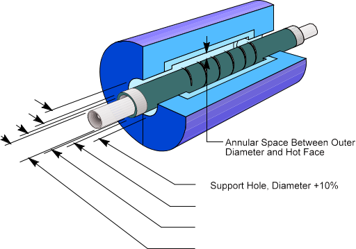
The furnace heated chamber dimension, which the sic heating elements spans, can be the same as the sic elements hot zone as shown The recommended terminal hole diameter is calculated by increasing the sic heating element outer diameter by 20% for sizes up to and including 1-3/8 inch (35mm), and a 10% increase for larger sizes. Table C shows these recommended minimum refractory hole diameters based on the Sic heating element size
Table C | |||
QS Heater | Recommended | ||
MM | Inch | MM | Inch |
13 | 1/2 | 16 | 5/8 |
16 | 5/8 | 19 | 3/4 |
19 | 3/4 | 23 | 7/8 |
22 | 7/8 | 27 | 1-1/16 |
25 | 1 | 30 | 1-3/16 |
32 | 1-1/4 | 39 | 1-1/2 |
35 | 1-3/8 | 42 | 1-5/8 |
38 | 1-1/2 | 42 | 1-11/16 |
44 | 1-3/4 | 49 | 1-15/16 |
54 | 2-1/8 | 60 | 2-3/8 |
70 | 2-3/4 | 77 | 3-1/32 |
Recommended Minnium | |||
44 | 1-3/4 | 49 | 1-15/16 |
50 | 2 | 55 | 2-1/4 |
55 | 2-1/8 | 61 | 2-11/16 |
62 | 2-1/2 | 69 | 2-3/4 |
75 | 3 | 84 | 3-5/16 |
Sic heating element should not be placed closer than two sic elements diameters to each other or one and one half sic elements diameter to a wall or other reflecting body. If the sic elements is not able to dissipate heat energy equally in all directions, it may overheat and possibly fail.
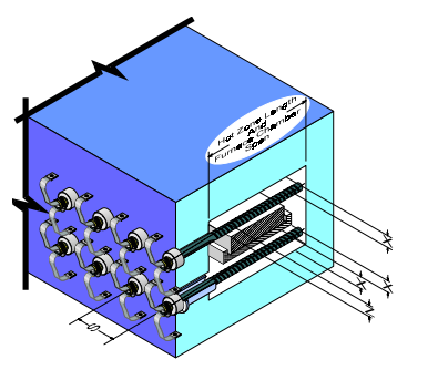
The formula for computing the recommended sic elements spacing to obtain an even temperature gradient on the product being heated is shown in Figure 3, below
RECOMMENDED SER STARBAR SPACING
X = 2 x Starbar diameter is the minimum, 1.5 x Starbar diameter is the absolute minimum and requires a reduced Starbar surface watt loading
Z = S ÷ 1.41 minimum for stationary loads
Z = S ÷ 1.73 minimum for moving loads
S = 2 x Starbar diameters minimum
X - distance from the centerline of Starbar to any reflecting surface, such as a refractory wall or product
Z - distance from the centerline of the Starbar to a moving or stationary load
S - distance from centerline of the Starbar to the centerline of an adjacent Starbar
QS SGR Positioned Horizontally
QS SGR used as Tube Heater
QS SGR element installation
QS SR elements are suitable for both horizontal and vertical installation.
As with QS SG elements, care must be taken when unpacking and handling QS SGR elements, so that they are not subjected to mechanical shock. Elements should always be supported using both hands.
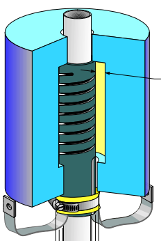
The elements should be installed in an insulating, ceramic sleeve to prevent possible shorting between both cold end halves, because full element voltage exists along the entire length of the terminal.
Precautions must be taken to prevent the terminals from overheating, especially if the elements are operating at the higher end of their temperature range or if the roof lining is relatively thin. In most cases a 25 mm (1 in) thick pad of ceramic fiber fitted below the terminal assembly will be suffi- cient, providing the terminal boxes are adequately ventilated. In more severe cases it may be necessary to mount the elements through a separate support plate, fitted about 75 –100 mm (2.95 – 3.9 in) above the furnace casing, to allow a free flow of air or process gas over the exposed cold ends.
Sleeves must be manufactured from a refractory material capable of withstanding the maximum element temperature (which may be considerably higher than the furnace temperature) and should have a sufficiently high electrical resistivity to prevent conduction between both cold end halves at that temperature. Generally, a high alumina, low iron refractory or vacuum-formed ceramic fiber material will be most suitable.
Sleeves should be fitted from the outside of the furnace, in holes bored to a diameter that will ensure a loose fit, and the sleeves should never be cemented into position. The clearance holes should be drilled right through to the hot face as shown in Fig. 6, and the holes may be flared at the hot face to help prevent any contact between the elements and the lining.
Under no circumstances should the element hot zones be allowed to enter the element support holes as this will lead to localised overheating and premature failure.
Elements may also be installed vertically with the terminals at the base and should be located on an electrically insulating, heat resistant support fitted below the terminal end
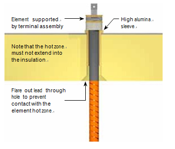
QS SGR vertical element
Special precautions are required where SGR elements are to be installed horizon- tally (Fig. 7), especially with long elements where support at both ends is required, and a longer than standard dump end should be specified when or- dering. In this case, the dump end must be support- ed on a hard smooth surface (a high alumina, low iron refractory) in such a way that the element is free to move laterally during heating and cooling. Although cantilevering of short QS
SGR elements may be possible, QS generally recommend that the dump end should always be supported. It is important to ensure that the dump end support is level and co-planer with the ceramic tube supporting the terminal end, otherwise the element may not be fully supported and may fail prematurely
QS SGR elements must always be installed so that the slots in the cold ends are hori- zontally aligned, otherwise tracking across both cold end halves may occur
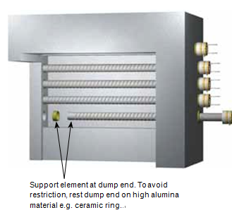
QS SGR horizontal element
Insure that there is clearance between the clamps and the furnace shell t RECOMMENDATIONS FOR CHANGING RR or SE ELEMENTS
1.With the furnace in operation, determine which elements require replacement. This may be accomplished through, visual inspection or by checking the current draw of each element with a clamp-on ammeter.
2.Turn off the electrical power and lock out the electrical disconnect.
3.Remove the clamps and the straps from the ends of those elements which require replacement.
4.Inspect the clamps to be sure that they hold the straps tightly to the element. If the clamp has lost its tension, it should be replaced.
5.Inspect the strap for fraying and oxidation. If the strap is frayed or has an oxidized powder on it, replace it.
6. Remove the two halves of the failed element if broken.
7. Inspect the refractory hole to insure there is no build up or deposition in the opening. If deposits exist, ream the hole or remove them. The hole should be larger than the element diameter .
8. If element guide sleeves are used, check them for cracks or build-up of condensation residue that could cause elements to be glued into position. Replace the sleeve if damage or condensation has occurred.
9. Check the alignment and straightness of the holes through the refractory. Any binding of the element can cause element breakage during heat up.
10. Slide the new element into the hot furnace quickly enough, so the aluminum at the end is not melted off but not so fast as to cause thermal shock. Avoid hitting the opposite wall with the element. Sometimes an alloy pipe can be used to guide the new element through the heating chamber. The element outside diameter fits inside the alloy pipe inside diameter in this process. Do not force the element into the terminal holes or exert any stress on the element during installation.
11. Center the element in the furnace chamber by insuring the same amount of element protrudes from each side of the furnace.
12. Lightly pack the open space around the element with bulk ceramic fiber. The bulk fiber should only be packed one half to one inch in from the cold face. After packing, the element should be easily rotated and must be free to expand upon heating. Never cement elements in place. Alternatively, use donut shaped washers made from ceramic fiber felt/blanket, with the ID of the washer made to the same diameter as the element. There is enough “give” in the fiber felt/blanket o be able to work the washers along the terminals for a snug fit. Carefully slide the fiber washers over the ends of the elements, and push up against the furnace casing.
13. Also pack the element inside diameter with bulk ceramic fiber to a depth of one inch, if this has not been done by QS This will reduce the temperature the straps and clamps will see.
14. Reconnect the straps and install the clamps on the aluminized ends of the element. Be sure the clamps and straps fit tightly to the radius of the element making a good electrical connection. Be sure there is slack in the straps, since the elements will expand and grow in length due to heating.
o prevent electrical short circuiting here.
16. Remove the electrical lock and turn the power back on. Visually inspect the elements for proper operation or check the elements for appropriate current draw using a clamp on ammeter.
17. Check the terminal connections to insure no arcing is evident.
18.Turn off the electrical power and lock out the electrical disconnect.
19.Carefully reinstall all guards or shields without hitting the elements
20.Remove the electrical lock and turn the power back on again.
21. Be sure to reset the rotary tap switches to the lowest setting after changing all elements in a furnace zone. This may not be possible if only one or two elements are changed. If rotary tap switches are not available, insure that the elements are operating on the lowest transformer tap to prevent element overloading and premature aging while still being able to maintain the furnace control temperature

 martin@qs-heatingelements.com
