General discription
Silicon carbide is a resistance type heating element.and made from high density reaction-bonded silicon carbide or high purity recrystallized silicon carbide , that are extruded in the form of rods or tubes, before being bonded together by a process of re crystallization, at temperatures of over 2500°C (4530°F). The firing process ensures the creation of rods with strong uniform bonds between adjacent grains, and the particle size distribution is closely controlled to ensure optimum density and resistance to the process atmosphere.
Heating elements for element temperatures up to 1625°C (2927°F), available in a wide variety of standard sizes and geometries, or in customized designs to meet the specific needs of various processes and equipment. heating elements are capable of high power output, and may be mounted either vertically or horizontally. no special supports are required
Grade 1 QS1
SiC heating Elements suitable for most applications in which silicon carbide elements are used. heating elements feature hot zones of high purity recrystallized silicon carbide, optimized for resistance to oxidation and common process gases. Available in rod or multi-leg designs. high density -- approximately 2.52 g/cm3 or 2.7g/cm3 to 2.8 g/cm3.This gives the heating elements very slow aging characteristics and high strength
Grade 2 QS2
SiC heating elements designed for the most challenging applications where conventional silicon carbide elements are unsuitable. SiC heating elements feature hot zones of high density, low permeability, reaction-bonded silicon carbide, which is highly resistant to oxidation, and to chemical attack by process volatiles and reactive atmospheres. At 2.7 g/cm3, this high-density low-porosity element has an extremely slow aging characteristic.


Item# | Daimeter | maximum overall length | Hot Zone(Electrical Resistance) | Cold End (Electrical Resistance) |
DH&DL | 10mm | 660mm | 0.01372 Ohms/mm | 0.000686 Ohms/mm |
DH&DL | 11mm | 915mm | 0.01009 Ohms/mm | 0.000505 Ohms/mm |
DH&DL | 13mm | 1090mm | 0.00773 Ohms/mm | 0.000387 Ohms/mm |
DH&DL | 16mm | 1250mm | 0.00497 Ohms/mm | 0.000248 Ohms/mm |
DH&DL | 19mm | 1575mm | 0.00341 Ohms/mm | 0.00017 Ohms/mm |
DH&DL | 25mm | 1900mm | 0.00197 Ohms/mm | 0.000098 Ohms/mm |
DH&DL | 32mm | 2210mm | 0.00134 Ohms/mm | 0.000067 Ohms/mm |
DH&DL | 35mm | 2290mm | 0.00106 Ohms/mm | 0.000053 Ohms/mm |
DH&DL | 38mm | 2340mm | 0.00092 Ohms/mm | 0.000046 Ohms/mm |
DH&DL | 45mm | 2670mm | 0.00065 Ohms/mm | 0.000032 Ohms/mm |
DH&DL | 54mm | 3300mm | 0.00059 Ohms/mm | 0.00003 Ohms/mm |
DH&DL | 70mm | 3300mm | 0.007298 Ohms/mm | 0.00052 Ohms/mm |
Physical properties
Bulk Density | 2.5—2,8g/℃m3 |
Porosity | 20% |
Thermal Conductivity | 14-19w/m ℃ |
Rupture Strength | 50Mpa(25℃) |
Specifi Heat | 1.okj/℃(25-1300℃) |
Coefficient of Thermal Expansion | 4.5x10⁻⁶(1000℃ |
OPERATING TEMPERATURES
SLIOCON CARBIDE HEATING ELEMENT USE BY ATMOSPHERE | ||||
ATMOSPHERES | TEMPERATURE LIMIT | MXXIMUM LOADING W/in2 | MXXIMUM LOADING W/cm2 | EFFECT |
CLEAN DRY AIR | 1550℃ | Maximum | Maximum | One piece Sic element can be operated at furnace control temperatures up to 1600ºC. (Maximum element temperature is 1625ºC). The three-piece Sic element is limited to 1427ºC. |
HYDROGEN | 1300℃ | 30 | 5 | An atmosphere which contains any percentage of hydrogen whatsoever will react with silicon carbide if the temperature exceeds 1300ºC. |
AMMONIA | 1300℃ | 30 | 5 | Reduces silica film, Frorm CH4 from Sic |
NITROGEN | 1370℃ | 30 | 5 | Form insulating Silicon Nitrides |
PURE OXYGEN | 1315℃ | 25 | 4 | Faster oxidization than in air. Use LMA infusion glaze cotated heating elements elements, or type TW, SE,SER or SEU |
CO2 | 1500℃ | 25 | 4 | No effect,may deposit Carbon |
CO | 1540℃ | 25 | 4 | No effect |
ARGON/HELIUM | 1700℃ | Maximum | Maximum | No detrimental effect |
WATER DP 60°F | 1095℃ | 30 | 5 | Reacts with Sic to form Silicon Hydrates ,Use LMA infusion glaze coated heating elements elements, or type TW,SE,SER,or SEU. |
HALOGENS | 700℃ | 25 | 4 | Attacks Sic and SiO2 reducing |
HYDROCARBONS | 1315℃ | 20 | 3 | Hot spotting from C pick-up |
METHANE | 1315℃ | 20 | 3 | Hot spotting from C pick-up |
DRY EXOTHERMIC GAS | 1400℃ | Maximum | Maximum | Dependent on composition |
DRY ENDOTHERMIC GAS | 1250℃ | Maximum | Maximum | Dependent on composition |
VACUUM | 1205℃ | 25 | 4 | To 7 Microns -Below vaporizes Sic. Short term use only |
S and SO2 | 1315℃ | 25 | 4 | Attack Sic |
For atmospheres containing water vapor, alkali metal vapors, flux vapors, or oxygen enrichment, we recommend the use of QS3 glaze coated elements
Glazes and coatings
Special glazes and surface treatments have been developed which can extend element life in various operating conditions, particularly where chemical attack is a problem. Details of these will be provided on request.
QS offers a special coating for certain severe atmosphere applications.
QS1 Coating
This coating consists of a complex silicate glass specially formulated to provide a high degree of protection against chemical attack in atmospheres containing water vapor, alkaline metal vapors, flux vapors and in applications that utilize oxygen enrichment, including; non-ferrous metal melting and holding, glass melting and refining, brazing, sintering of powdered metal components, and pre-sintering of powders for lithiumion battery cells.
QS2 Coating
This coating is a silicon carbide/silica composite. It is applied in 2 parts, an organic based pretreatment followed by a mix of silicon carbide and colloidal silica. The coating is cured to provide an adherent coating that covers the outside surface of the heating element. The organic portion burns away during the cure step to leave SiC and SiO2. This coating acts as a physical barrier to chemical attack on the heating elements.
QS3 Coating
This coating is a zirconia/silica based coating. When applied to the hot zone, this coating acts as a physical barrier to attack. When applied to the cold ends, the coating prevents the elements from sticking to the furnace refractor
SERVICE LIFE
All silicon carbide elements increase in resistance during their life in operation, This characteristic of increasing in resistance is called aging. Aging is a function of the following:
•Furnace temperature
•Element surface loading in W/cm2
•Atmosphere surrounding the elements
•Mode of operation – continuous or intermittent
•Operating practices and power control methods used
•Operating and maintenance technique
As a general guide, QS SIC elements may increase in resistance at a rate of about 5 – 6% per 1000 hours operating continuously in clean air at a temperature of 1400°C ( and at about 3% per 1000 hours use at 1000°C . It should be noted that small changes in operating conditions can alter these rates considerably
INTERCHANGEABILITY
QS SIC are premier grade high performance silicon carbide elements, and we are the only high quality silicon carbide heating elements manufactured in theCHINA. Elements can also be manufactured in special sizes and resistance values to replace elements supplied by other manufacturers in Asia and Europe. It is important to provide the nominal electrical resistance when ordering Sic elements.
EASE OF REPLACEMENT
SIC element can be replaced while the furnace is at operating temperature. The power to the elements being changed should be shut off, the spring clips and aluminum braid released, and the old SIC removed. The new SIC should be inserted smoothly through the hot furnace with sufficient speed to insure that the aluminum is not melted off the terminal end but not so fast as to cause thermal shock
AVAILABILITY
SIC can be shipped from stock, or two to three weeks after receipt of an order. In an emergency we may be able to produce more quickly.
CUSTOM CONFIGURATIONS
Special sizes and shapes are available. Cold ends can be different lengths. This, for example, would be applicable for furnaces with arched roofs that require longer cold ends through the roof and shorter through the floor. Another modification is a multiple-temperature hot zone. This, for example, would be helpful to get additional heat energy into the lower, more densely loaded tunnel kiln. While this special modified hot zone may not create a specific temperature differential, it does offer a convenient way to get more or less heat energy.
SUPERIOR PERFORMANCE
SIC elements will give you superior performance due to their high density -- approximately 2.52 g/cm3 .or 2.7 g/cm3to2.8 g/cm3 ,This gives the SIC elements very slow aging characteristics and high strength.
Ordering
The minimum information required when ordering QS SIC elements is as follows:
Element type:
Diameter, mm (ØA):
Hot zone length, mm(L):
Overall length, mm (L):
Nominal resistance,( Ω):
ELECTRICAL CHARACTERISTICS
The silicon carbide element is a linear type resistance heater that converts electrical energy to heat energy.The SIC hot zone is a self-bonded alpha silicon carbide. The lattice structure or bonds that hold the silicon carbide grains together are formed by recrystallizing the silicon carbide at very high temperatures (>2500C). SIC are manufactured from green silicon carbide, which is classed as an excess electron type semiconductor. The electrical resistance of a SIC is difficult to measure at room temperature due to minor impurities, self heating, and contact resistance. Also the green silicon carbide has a negative resistance temperature characteristic from room temperature to approximately 650ºC. It turns positive at this point and remains so throughout its normal operating temperature range. A typical resistance temperature characteristic curve of a heating elements is shown . Nominal SIC resistance is measured at the calibrating temperature of 1071C. Nominal resistance values of SIC in ohms per unit of length are shown in Table A,
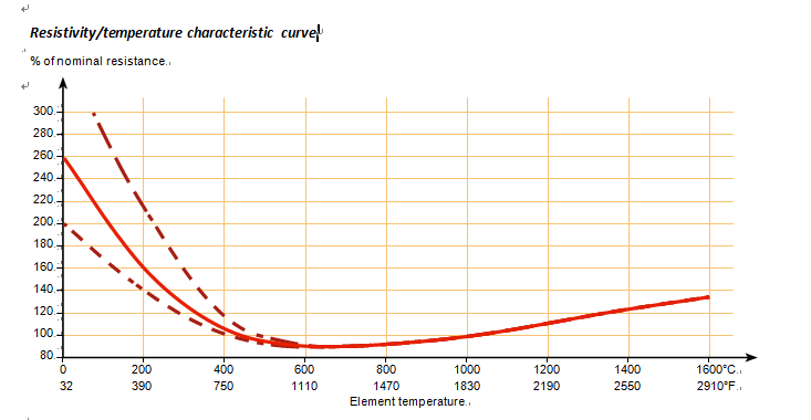
Table A | |||||||
RR Dimensions | RR Electrical Resistance | ||||||
Nominal Element Diameter | Max.Rec. | Ohms Hot Zone | Ohms Cold Ends | ||||
mm | Inch | mm | Inch | Ohms/mm | Ohms/Inch | Ohms/mm | Ohms/Inch |
10 | 3/8 | 355 | 14 | 0.01372 | 0.3486 | 0.000686 | 0.01743 |
11 | 7/16 | 355 | 14 | 0.01009 | 0.2563 | 0.000505 | 0.01282 |
13 | 1/2 | 560 | 22 | 0.00773 | 0.1963 | 0.000387 | 0.00982 |
16 | 5/8 | 610 | 24 | 0.00497 | 0.1262 | 0.000248 | 0.00631 |
19 | 3/4 | 863 | 34 | 0.00341 | 0.8650 | 0.000170 | 0.00433 |
25 | 1 | 1220 | 48 | 0.00197 | 0.0500 | 0.000098 | 0.00250 |
32 | 1-1/4 | 1524 | 60 | 0.00134 | 0.0343 | 0.000067 | 0.00171 |
35 | 1-3/8 | 1524 | 60 | 0.00106 | 0.0270 | 0.000053 | 0.00135 |
38 | 1-1/2 | 1727 | 68 | 0.00092 | 0.0234 | 0.000046 | 0.00117 |
44 | 1-3/4 | 1981 | 78 | 0.00065 | 0.0165 | 0.000032 | 0.00082 |
54 | 2-1/8 | 4400 | *173 | 0.00059 | 0.0150 | 0.000030 | 0.00075 |
70 | 2-3/4 | 4400 | *173 | 0.00029 | 0.0073 | 0.000020 | 0.00052 |
|
|
|
|
|
|
| |
Surface temperature at various watt loadings

Element surface temp(c) and Furnace Temp(c)
QS Element temperature °C , vs Surface load and Furnace temperature

X
Applications
Elements are used in a wide variety of furnace applications, from small labora- tory furnaces to large industrial heating processes, in different atmospheres and temperature ranges.
CERAMIC FIRING | HEATING ELEMENT | MELTING | HOLDING | ASSAYING PRECIOUS METALS | INCINERATION AND REGENRATION |
Ferrites | Tools | Non-ferrous (aluminum, magnesium, copper) | Non-ferrous (Aluminum, magnesium, copper) | Gold | Burning Organic Wastes |
Spark Plugs | Geras | Glass | Silver | Carbon Regeneration of Removal of Organics | |
Space Shuttle Tiles | Dies | Float Glass (Tin Bath) | |||
Graphite Shapes | Shafts | ||||
Phosphorescent Powders | Fluidized Bed Designs |
SINTERING POWERED METALS | BRAZING | FORGING | ANNEALING | Laboratory Research |
Iron Parts | Copper | Billet Heating | Bright Annealing of Stainless Steel | Thermal Conductivity |
Alloy Parts | Alloy Steels | Hand Tools | Stress Relieving | Thermal Expansion |
Non-Ferrous Parts | Silver | Automotive & Aircraft Valves | Glass | Flammability Testing |
Basic Powders & Grains | Tungsten Carbide | Jet Engine Blades | Modulus of Rupture Testing | |
|
| Infrared Spectometry |
In many applications including: glass, ceramics, electronics and metal industries, and also for re- search and development. Examples of some typical furnaces where QS SIC elements are the natural choice are illustrated below:


SPECIFICATIONS AND MATCHING
SIC have a
manufactured tolerance of ±20% on the nominal resistance. All SIC are
calibrated at least twice prior to shipping to ensure their being within
specifications. The calibrated amperage of each Sic elements is marked
on the carton and on the right hand end of each sic elements.
When
installing, arrange sic elements with amperage values as close to each
other as available. Longer service life will be obtained when series
connected sic elements are matched in resistance. SIC are shipped as
closely matched as possible.
MATCHING SILICON CARBIDE HEATING ELEMENTS
We
are very particular in the matching of the amps supplied in a given
shipment to help give you the best matching that we can.
The reason for matching is to improve the heating element life and to improve the temperature uniformity in the furnace chamber. Your primary concern is for improving heating element life
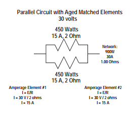
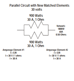
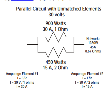
.The reason for having elements that are matched in resistance in a set is to keep the surface temperature of the elements as nearly the same value as possible. If there is a large variation in resistance, there will be a large difference in surface temperature. Normally a 10% difference in resistance is acceptable.
An all parallel electrical heating element arrangement is preferable to a series arrangement for the higher resistance element will operate at a lower surface temperature for the higher resistance element will be providing less power. This also has a self-balancing characteristic. Conversely in an all series arrangement, the highest resistant element will be the highest in temperature. Therefore, matching of elements when connected in series is more important than when connected in parallel. Before shipping, we always select the closest matched elements from those we have available.
We have a chart that we work from. The smaller diameter elements are normally in larger sets than the larger diameter elements This coincides with normal furnace design in that large diameter elements are usually installed in smaller sets.
We always try to match to a customer’s specifications and will contact the customer should we have trouble meeting his matching specifications. The size of a set is determined by the number of elements connected to a transformer tap switch.
If you could control the voltage to each element you need not be concerned about matching. Matching of the Sic elements is done by current rather than by resistance, for it is a more convenient value for us to use.
The ampere values used for matching are written in black marker on the end of the element carton and also in white crayon on the cold end of the heating element.
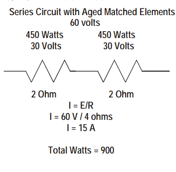
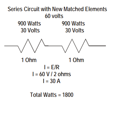
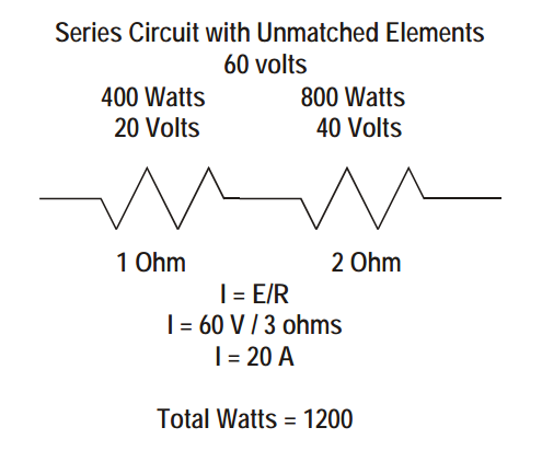
FURNACE HEATING CHAMBER
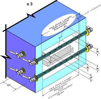
The furnace heated chamber dimension, which the SIC spans, can be the same as the hot zone length of the Sic elements as shown by the SIC under the load in Figure 3. Alternately the furnace heating chamber dimension, which the SIC spans, can be 25mm less than the effective heating length of the SIC. In this case there must be a 45 conical recess in the furnace wall as shown in Figure 3 for the SIC above the load. Recommended terminal hole diameters for various refractory walls and SIC sizes are shown in Table B. SIC should not be placed closer than two SIC diameters to each other or one and one half SIC diameters to a wall or other reflecting body. If the SIC is not able to dissipate heat energy equally in all directions, it may cause local overheating and possible failure
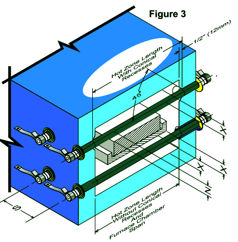
Recommended Sic heating elements Spacing
X = 2 × Sic element diameter is the Minimum,
1.5 × Sic element diameter is the absolute Minimum and requires a reduced Sic heating element Surface Watt Loading
Z = S ÷ 1.41 Minimum for Stationary Loads
Z = S ÷ 1.73 Minimum for Moving Loads
S = 2 × Sic element diameter Minimum
X - is the distance from the centerline of the heating elements to any other reflecting surface, such as a refractory wall or product
Z - is the distance from the centerline of the Sic heating element to a moving or stationary load
S - is the distance from the centerline of the Sic heating element to the centerline of an adjacent Sic heating element.
Table B | |||||||||||
Minimum Hole Diameter Based on Refractory Wall Thickness | |||||||||||
Nominal QS Dia. | 100 | 150 | 200 | 300 | 400 | 3 | 5 | 6.5 | 9 | 13.5 | |
mm | Inch | mm | mm | mm | mm | mm | Inch | Inch | Inch | Inch | Inch |
10 | 3/8 | 15 | 15 | 16 |
|
| 9/16 | 9/16 | 5/8 |
|
|
11 | 7/16 | 16 | 17 | 18 | 20 |
| 5/8 | 11/16 | 11/16 | 3/4 |
|
13 | 1/2 | 18 | 19 | 20 | 22 | N/A | 11/16 | 3/4 | 3/4 | 13/16 | N/A |
16 | 5/8 | 21 | 22 | 23 | 25 | N/A | 13/16 | 7/8 | 7/8 | 15/16 | N/A |
19 | 3/4 | 25 | 25 | 26 | 28 | N/A | 15/16 | 1 | 1 | 1-1/16 | N/A |
25 | 1 | 31 | 32 | 33 | 35 | 37 | 1-3/16 | 1-3/16 | 1-1/4 | 1-1/4 | 1-7/16 |
32 | 1-1/4 | 38 | 38 | 40 | 42 | 44 | 1-1/2 | 1-1/2 | 1-9/16 | 1-9/16 | 1-11/16 |
35 | 1-3/8 | 41 | 42 | 43 | 45 | 47 | 1-5/8 | 1-5/8 | 1-11/16 | 1-11/16 | 1-11/16 |
38 | 1-1/2 | 44 | 44 | 46 | 48 | 50 | 1-3/4 | 1-3/4 | 1-13/16 | 1-7/8 | 1-15/16 |
44 | 1-3/4 | 51 | 52 | 53 | 55 | 57 | 2 | 2-1/16 | 2-1/16 | 2-1/8 | 2-3/16 |
54 | 2-1/8 | 61 | 62 | 63 | 65 | 67 | 2-3/8 | 2-7/16 | 2-7/16 | 2-1/2 | 2-9/16 |
70 | 2-3/4 | 79 | 79 | 79 | 81 | 83 | 3-1/8 | 3-1/8 | 3-1/8 | 3-3/16 | 3-1/4 |
MOUNTING
There are no restrictions on the mounting positions of SIC, although horizontal and vertical orientation are the more common. Extreme caution should be used when mounting to ensure that the SIC are not placed in tension. There should be adequate freedom to allow for the furnace and SIC to expand and contract independently. When mounting SIC vertically, they must be supported on the lower end by electrically insulated supports, or from above using support pins on an isolating plate of sufficient strength to support the weight of the elements. The SIC ends should extend beyond the furnace cold face by a minimum distance of 3 to 4 inches or 3 × the element diameter (whichever is greater). When using sealed terminal boxes, extend the cold ends by a minimum of 4-5 × the element diameter. heating elements should have their heating sections centered in the furnace chamber so that no portion of the heating section extends into the furnace wall. A conical or truncated cone shaped recess 1/2 inch (13mm) deep is sometimes located on each interior wall where the heating elements passes through. This allows the hot zone to radiate properly and helps maintain a uniform temperature in the kiln.
DH&DL SIC element installation
Although silicon carbide is rigid and self support- ing, it has a fairly low impact strength, and care must be taken when unpacking and handling the elements so that they are not subjected to mechani- cal shock. Elements should always be supported in two hands.
It is important to ensure that the elements are not restricted in any way and are free to move radially, as well as axially, in their support holes. Element holes must be in line, and the whole alignment should be checked by passing a straight bar, of the same diameter as the support holes, right through the furnace, before fitting the elements
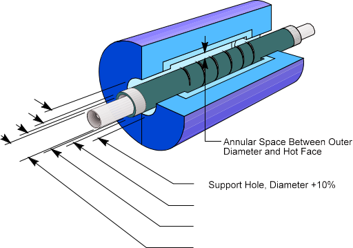
Under no circumstances should the element hot zones be allowed to enter the element support holes as this will lead to localized overheating and premature failure Special lead-in sleeves are available for mounting all diameters of QS SIC elements and these are detailed and in the accessories size list. Sleeves should be fit from the outside of the furnace, in holes bored to a diameter that will ensure a loose fit, and the sleeves should never be cemented into position. In general, the sleeves will be far shorter than the thickness of the furnace insulation, but the clearance holes should be drilled right through to the hot face, as shown in the follow to prevent any contact between the elements and the lining, as this can lead to adhesion, and premature failure. If sleeves are not to be used, for example in brick- lined furnaces, then the elements may be fit through holes about 4 – 5 mm (1/6 –1/5 in) larger than the element diameter for element sizes up to 20 mm (3/4 in), and about 8 –10 mm (1/3 in) larger for elements from 25 – 55 mm (1 – 2 1/8 in) diameter.
Even larger holes may be required where there is a possibility of volatiles condensing in the element holes or on to the cold ends, or where the furnace lining is exceptionally thick.
Elements should always be centralized by support- ing each cold end on a small pad of ceramic mate- rial, to prevent contact between the element cold ends, and the lead-in holes. Under no circumstances should the cold ends be wrapped with ceramic fiber or other insulation, as this will lead to restriction and possible premature failure.
To prevent radiation on to the terminal connections and minimize heat losses, a flexible ceramic fiber washer may be fit over each terminal end and positioned so that it rests against the outer face of the furnace
In all cases, the element ends should extend beyond the sleeve flange, or the outer face of the fiber washer, by a distance of approximately 2 – 3 times the element diameter
The use of aluminum braid is recommended for making terminal connections as it does not suffer from progressive oxidation and is sufficiently flat and soft to allow a good connection to be made.
Braids are normally attached using type H spring clips, which are easy to install and require no tools. Where space is restricted, type C clips may be used, and these require a special tool for installation.
Both H and C clips rely on spring steel to maintain a good contact, and must be maintained at a tem- perature below about 250°C . For higher temperatures, types G and D clamps may be used.
These are clamped to the elements using stainless steel set screws, and high temperature lubricant should be applied to the threads before installation, to prevent seizing, and later difficulty in tightening and removal. Screws should be retightened after 24 hours use.
Element connections must be kept reasonably cool and any terminal guards fit should be well venti- lated.
Where sealed terminal boxes are essential, for example in controlled atmosphere furnaces, then the following procedures should be followed:
•Increase the free length of cold end outside the furnace to 4 – 5 times the element diameter
•Ensure that the surface area of the terminal covers is sufficient to ensure adequate cooling.
It may be necessary to provide finned covers to increase the surface area
•Use type D terminal clamps, and larger section connecting braids than normal
•Introduce a proportion of the process gas via the terminal boxes, to assist in cooling
•In very severe cases, some kind of forced cooling may be required
Where QS SIC elements are to be mounted vertically, a support of electrically insu- lating, heat-resistant material should be provided below the terminal end. Alternatively, elements of 16 mm diameter and above may be supplied to special order with support slots and washers to allow them to be suspended from the top of the furnace,

RECOMMENDATIONS FOR CHANGING RR or SE ELEMENTS
1.With the furnace in operation, determine which elements require replacement. This may be accomplished through, visual inspection or by checking the current draw of each element with a clamp-on ammeter.
2.Turn off the electrical power and lock out the electrical disconnect.
3.Remove the clamps and the straps from the ends of those elements which require replacement.
4.Inspect the clamps to be sure that they hold the straps tightly to the element. If the clamp has lost its tension, it should be replaced.
5.Inspect the strap for fraying and oxidation. If the strap is frayed or has an oxidized powder on it, replace it.
6. Remove the two halves of the failed element if broken.
7. Inspect the refractory hole to insure there is no build up or deposition in the opening. If deposits exist, ream the hole or remove them. The hole should be larger than the element diameter (See table B on page 7 of our RR brochure).
8. If element guide sleeves are used, check them for cracks or build-up of condensation residue that could cause elements to be glued into position. Replace the sleeve if damage or condensation has occurred.
9. Check the alignment and straightness of the holes through the refractory. Any binding of the element can cause element breakage during heat up.
10. Slide the new element into the hot furnace quickly enough, so the aluminum at the end is not melted off but not so fast as to cause thermal shock. Avoid hitting the opposite wall with the element. Sometimes an alloy pipe can be used to guide the new element through the heating chamber. The element outside diameter fits inside the alloy pipe inside diameter in this process. Do not force the element into the terminal holes or exert any stress on the element during installation. Page 1
11. Center the element in the furnace chamber by insuring the same amount of element protrudes from each side of the furnace.
12. Lightly pack the open space around the element with bulk ceramic fiber. The bulk fiber should only be packed one half to one inch in from the cold face. After packing, the element should be easily rotated and must be free to expand upon heating. Never cement elements in place. Alternatively, use donut shaped washers made from ceramic fiber felt/blanket, with the ID of the washer made to the same diameter as the element. There is enough “give” in the fiber felt/blanket o be able to work the washers along the terminals for a snug fit. Carefully slide the fiber washers over the ends of the elements, and push up against the furnace casing.
13. Also pack the element inside diameter with bulk ceramic fiber to a depth of one inch, if this has not been done by I Squared R. This will reduce the temperature the straps and clamps will see.
14. Reconnect the straps and install the clamps on the aluminized ends of the element. Be sure the clamps and straps fit tightly to the radius of the element making a good electrical connection. Be sure there is slack in the straps, since the elements will expand and grow in length due to heating.
15. Insure that there is clearance between the clamps and the furnace shell to prevent electrical short circuiting here.
16. Remove the electrical lock and turn the power back on. Visually inspect the elements for proper operation or check the elements for appropriate current draw using a clamp on ammeter.
17. Check the terminal connections to insure no arcing is evident.
18.Turn off the electrical power and lock out the electrical disconnect.
19.Carefully reinstall all guards or shields without hitting the elements
20.Remove the electrical lock and turn the power back on again.
21. Be sure to reset the rotary tap switches to the lowest setting after changing all elements in a furnace zone. This may not be possible if only one or two elements are changed. If rotary tap switches are not available, insure that the elements are operating on the lowest transformer tap to prevent element overloading and premature aging while still being able to maintain the furnace control temperature
RECOMMENDED SE heating elements SPACING
X - Distance from the centerline of heating elements to any reflecting surface, such as a refractory wall or produc
Z - Distance from the centerline of the heating elements to a moving or stationary load
S - Distance from centerline of the heating elements to the centerline of an adjacent heating elements
X = 2 x heating elements diameter is the minimum,
1.5 x heating elements diameter is the absolute minimum and requires a reduced heating elements surface watt loading
Z = S/1.41 minimum for stationary loads
Z = S/1.73 minimum for moving loads.
S = 2 x heating elements diameters minimum
Installation methods
QS SG element installation Although silicon carbide is rigid and self support- ing, it has a fairly low impact strength, and care must be taken when unpacking and handling the elements so that they are not subjected to mechani- cal shock. Elements should always be supported in both hands.

It is important to ensure that the elements are not restricted in any way and are free to move radially, as well as axially, in their support holes. Element holes must be in line, and the hole alignment should be checked by passing a straight bar, of the same diameter as the support holes, right through the furnace, before fitting the elements.
Under no circumstances should the element hot zone be allowed to enter the element support holes as this will lead to localised overheating and premature failure.
Special lead-in sleeves are available for installing all diameters of QS SG and SR elements and these are detailed iand in the Accessories size list. Sleeves should be fitted from the outside of the furnace, in holes bored to a diameter that will ensure a loose fit, and the sleeves should never be cemented into position.
In general, the sleeves will be far shorter than the thickness of the furnace insulation, but the clearance holes should be drilled right through to the hot face, as shown , to prevent any contact between the elements and the lining, as this can lead to adhesion, and premature failure.
If sleeves are not to be used, for example in brick-lined furnaces, then the elements may be fitted through holes about 4 – 5 mm (0.16 – 0.2 in) larger than the element diameter for element sizes up to 19 mm (0.75 in), and about 8 –10 mm
(0.31 – 0.39 in) larger for elements from 25 – 54 mm (1 – 2.13 in) diameter.
Even larger holes may be required where there is a possibility of volatiles condensing in the element holes or on to the cold ends, or where the furnace lining is exceptionally thick.
Elements should always be centralised by supporting each cold end on a small pad of ceramic material, to prevent contact between the element cold ends, and the lead-in holes. Under no cir- cumstances should the cold ends be wrapped with ceramic fiber or other insulation, as this will lead to restriction and possible premature failure.
To prevent radiation on to the terminal connections and minimise heat losses, a flexible ceramic fiber washer may be fitted over each terminal end and positioned so that it rests against the outer face of the furnace .
In all cases, the element ends should extend beyond the sleeve flange, or the outer face of the fiber washer, by a distance of approximately 2 – 3 times the element diameter.
The use of aluminum braid is recommended for making terminal connections as it does not suffer from progressive oxidation and is sufficiently flat and soft to allow a good connection to be made. Braids are normally attached using type HC spring clips, which are easy to install and require no tools.
Where space is restricted, type CC clips may be used, and these require a special tool for installa- tion. Both HC and CC clips rely on spring steel to maintain a good contact, and must be maintained at a temperature below about 250°C (480°F). For higher temperatures, types G or D clamps may be used. These are clamped to the elements using stainless steel set screws, and high temperature lubricant should be applied to the threads before installation, to prevent seizing and later difficulty in tightening and removal. Screws should be re- tightened after 24 hours use.
Element connections must be kept reasonably cool and any terminal guards fitted should be well ventilated. Where sealed terminal boxes are essential, for example in controlled atmosphere furnaces, then the following procedures should be followed:
•Increase the free length of cold end outside the furnace to 4–5 times the element diameter.
•Ensure that the surface area of the terminal covers is sufficient to ensure adequate cooling.
It may be necessary to provide finned covers to increase the surface area.
•Use type D terminal clamps, and larger section connecting braids than normal.
•Introduce a proportion of the process gas via the terminal boxes, to assist in cooling.
•In very severe cases, some kind of forced cooling may be required.
Where QS SG elements are to be installed vertically, a support of electrically insulat- ing, heat-resistant material should be provided below the terminal end.
RECOMMENDATIONS FOR CHANGING RR or SE ELEMENTS
1.With the furnace in operation, determine which elements require replacement. This may be accomplished through, visual inspection or by checking the current draw of each element with a clamp-on ammeter.
2.Turn off the electrical power and lock out the electrical disconnect.
3.Remove the clamps and the straps from the ends of those elements which require replacement.
4.Inspect the clamps to be sure that they hold the straps tightly to the element. If the clamp has lost its tension, it should be replaced.
5.Inspect the strap for fraying and oxidation. If the strap is frayed or has an oxidized powder on it, replace it.
6. Remove the two halves of the failed element if broken.
7. Inspect the refractory hole to insure there is no build up or deposition in the opening. If deposits exist, ream the hole or remove them. The hole should be larger than the element diameter (See table B on page 7 of our RR brochure).
8. If element guide sleeves are used, check them for cracks or build-up of condensation residue that could cause elements to be glued into position. Replace the sleeve if damage or condensation has occurred.
9. Check the alignment and straightness of the holes through the refractory. Any binding of the element can cause element breakage during heat up.
10. Slide the new element into the hot furnace quickly enough, so the aluminum at the end is not melted off but not so fast as to cause thermal shock. Avoid hitting the opposite wall with the element. Sometimes an alloy pipe can be used to guide the new element through the heating chamber. The element outside diameter fits inside the alloy pipe inside diameter in this process. Do not force the element into the terminal holes or exert any stress on the element during installation. Page 1
11. Center the element in the furnace chamber by insuring the same amount of element protrudes from each side of the furnace.
12. Lightly pack the open space around the element with bulk ceramic fiber. The bulk fiber should only be packed one half to one inch in from the cold face. After packing, the element should be easily rotated and must be free to expand upon heating. Never cement elements in place. Alternatively, use donut shaped washers made from ceramic fiber felt/blanket, with the ID of the washer made to the same diameter as the element. There is enough “give” in the fiber felt/blanket o be able to work the washers along the terminals for a snug fit. Carefully slide the fiber washers over the ends of the elements, and push up against the furnace casing.
13. Also pack the element inside diameter with bulk ceramic fiber to a depth of one inch, if this has not been done by I Squared R. This will reduce the temperature the straps and clamps will see.
14. Reconnect the straps and install the clamps on the aluminized ends of the element. Be sure the clamps and straps fit tightly to the radius of the element making a good electrical connection. Be sure there is slack in the straps, since the elements will expand and grow in length due to heating.
15. Insure that there is clearance between the clamps and the furnace shell to prevent electrical short circuiting here.
16. Remove the electrical lock and turn the power back on. Visually inspect the elements for proper operation or check the elements for appropriate current draw using a clamp on ammeter.
17. Check the terminal connections to insure no arcing is evident.
18.Turn off the electrical power and lock out the electrical disconnect.
19.Carefully reinstall all guards or shields without hitting the elements
20.Remove the electrical lock and turn the power back on again.
21. Be sure to reset the rotary tap switches to the lowest setting after changing all elements in a furnace zone. This may not be possible if only one or two elements are changed. If rotary tap switches are not available, insure that the elements are operating on the lowest transformer tap to prevent element overloading and premature aging while still being able to maintain the furnace control temperatur
FURNACE HEATING CHAMBER
The furnace heated chamber dimension, which the sic heating elements spans, can be the same as the sic elements hot zone as shown The recommended terminal hole diameter is calculated by increasing the sic heating element outer diameter by 20% for sizes up to and including 1-3/8 inch (35mm), and a 10% increase for larger sizes. Table C shows these recommended minimum refractory hole diameters based on the Sic heating element size
Table C | |||
QS Heater | Recommended | ||
MM | Inch | MM | Inch |
13 | 1/2 | 16 | 5/8 |
16 | 5/8 | 19 | 3/4 |
19 | 3/4 | 23 | 7/8 |
22 | 7/8 | 27 | 1-1/16 |
25 | 1 | 30 | 1-3/16 |
32 | 1-1/4 | 39 | 1-1/2 |
35 | 1-3/8 | 42 | 1-5/8 |
38 | 1-1/2 | 42 | 1-11/16 |
44 | 1-3/4 | 49 | 1-15/16 |
54 | 2-1/8 | 60 | 2-3/8 |
70 | 2-3/4 | 77 | 3-1/32 |
Recommended Minnium | |||
44 | 1-3/4 | 49 | 1-15/16 |
50 | 2 | 55 | 2-1/4 |
55 | 2-1/8 | 61 | 2-11/16 |
62 | 2-1/2 | 69 | 2-3/4 |
75 | 3 | 84 | 3-5/16 |
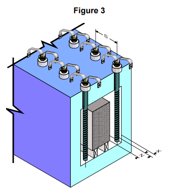
Sic heating element should not be placed closer than two sic elements diameters to each other or one and one half sic elements diameter to a wall or other reflecting body. If the sic elements is not able to dissipate heat energy equally in all directions, it may overheat and possibly fail.
The formula for computing the recommended sic elements spacing to obtain an even temperature gradient on the product being heated is shown in Figure 3, below
RECOMMENDED SER heating elements SPACING
X = 2 x heating elements diameter is the minimum,
1.5 x heating elements diameter is the absolute minimum and requires a reduced heating elements surface watt loading
Z = S ÷ 1.41 minimum for stationary loads
Z = S ÷ 1.73 minimum for moving loads
S = 2 x heating elements diameters minimum
X - distance from the centerline of heating elements to any reflecting surface, such as a refractory wall or product
Z - distance from the centerline of the heating elements to a moving or stationary load
S - distance from centerline of the heating elements to the centerline of an adjacent heating elements


QS SGR element installation
QS SR elements are suitable for both horizontal and vertical installation.
As with QS SG elements, care must be taken when unpacking and handling QS SGR elements, so that they are not subjected to mechanical shock. Elements should always be supported using both hands.
The elements should be installed in an insulating, ceramic sleeve to prevent possible shorting between both cold end halves, because full element voltage exists along the entire length of the terminal.
Precautions must be taken to prevent the terminals from overheating, especially if the elements are operating at the higher end of their temperature range or if the roof lining is relatively thin. In most cases a 25 mm (1 in) thick pad of ceramic fiber fitted below the terminal assembly will be suffi- cient, providing the terminal boxes are adequately ventilated. In more severe cases it may be necessary to mount the elements through a separate support plate, fitted about 75 –100 mm (2.95 – 3.9 in) above the furnace casing, to allow a free flow of air or process gas over the exposed cold ends.
Sleeves must be manufactured from a refractory material capable of withstanding the maximum element temperature (which may be considerably higher than the furnace temperature) and should have a sufficiently high electrical resistivity to prevent conduction between both cold end halves at that temperature. Generally, a high alumina, low iron refractory or vacuum-formed ceramic fiber material will be most suitable.
Sleeves should be fitted from the outside of the furnace, in holes bored to a diameter that will ensure a loose fit, and the sleeves should never be cemented into position. The clearance holes should be drilled right through to the hot face as shown in Fig. 6, and the holes may be flared at the hot face to help prevent any contact between the elements and the lining. Under no circumstances should the element hot zones be allowed to enter the element support holes as this will lead to localised overheating and premature failure.
Elements may also be installed vertically with the terminals at the base and should be located on an electrically insulating, heat resistant support fitted below the terminal end

Special precautions are required where SGR elements are to be installed horizon- tally (Fig. 7), especially with long elements where support at both ends is required, and a longer than standard dump end should be specified when or- dering. In this case, the dump end must be support- ed on a hard smooth surface (a high alumina, low iron refractory) in such a way that the element is free to move laterally during heating and cooling.
Although cantilevering of short QS SGR elements may be possible, QS generally recommend that the dump end should always be supported. It is important to ensure that the dump end support is level and co-planer with the ceramic tube supporting the terminal end, otherwise the element may not be fully supported and may fail prematurely
QS SGR elements must always be installed so that the slots in the cold ends are hori- zontally aligned, otherwise tracking across both cold end halves may occur

Insure that there is clearance between the clamps and the furnace shell t RECOMMENDATIONS FOR CHANGING RR or SE ELEMENTS
1.With the furnace in operation, determine which elements require replacement. This may be accomplished through, visual inspection or by checking the current draw of each element with a clamp-on ammeter.
2.Turn off the electrical power and lock out the electrical disconnect.
3.Remove the clamps and the straps from the ends of those elements which require replacement.
4.Inspect the clamps to be sure that they hold the straps tightly to the element. If the clamp has lost its tension, it should be replaced.
5.Inspect the strap for fraying and oxidation. If the strap is frayed or has an oxidized powder on it, replace it.
6. Remove the two halves of the failed element if broken.
7. Inspect the refractory hole to insure there is no build up or deposition in the opening. If deposits exist, ream the hole or remove them. The hole should be larger than the element diameter .
8. If element guide sleeves are used, check them for cracks or build-up of condensation residue that could cause elements to be glued into position. Replace the sleeve if damage or condensation has occurred.
9. Check the alignment and straightness of the holes through the refractory. Any binding of the element can cause element breakage during heat up.
10. Slide the new element into the hot furnace quickly enough, so the aluminum at the end is not melted off but not so fast as to cause thermal shock. Avoid hitting the opposite wall with the element. Sometimes an alloy pipe can be used to guide the new element through the heating chamber. The element outside diameter fits inside the alloy pipe inside diameter in this process. Do not force the element into the terminal holes or exert any stress on the element during installation.
11. Center the element in the furnace chamber by insuring the same amount of element protrudes from each side of the furnace.
12. Lightly pack the open space around the element with bulk ceramic fiber. The bulk fiber should only be packed one half to one inch in from the cold face. After packing, the element should be easily rotated and must be free to expand upon heating. Never cement elements in place. Alternatively, use donut shaped washers made from ceramic fiber felt/blanket, with the ID of the washer made to the same diameter as the element. There is enough “give” in the fiber felt/blanket o be able to work the washers along the terminals for a snug fit. Carefully slide the fiber washers over the ends of the elements, and push up against the furnace casing.
13. Also pack the element inside diameter with bulk ceramic fiber to a depth of one inch, if this has not been done by QS This will reduce the temperature the straps and clamps will see.
14. Reconnect the straps and install the clamps on the aluminized ends of the element. Be sure the clamps and straps fit tightly to the radius of the element making a good electrical connection.
15.Be sure there is slack in the straps, since the elements will expand and grow in length due to heating.
o prevent electrical short circuiting here.
16. Remove the electrical lock and turn the power back on. Visually inspect the elements for proper operation or check the elements for appropriate current draw using a clamp on ammeter.
17. Check the terminal connections to insure no arcing is evident.
18.Turn off the electrical power and lock out the electrical disconnect.
19.Carefully reinstall all guards or shields without hitting the elements
20.Remove the electrical lock and turn the power back on again.
21. Be sure to reset the rotary tap switches to the lowest setting after changing all elements in a furnace zone. This may not be possible if only one or two elements are changed. If rotary tap switches are not available, insure that the elements are operating on the lowest transformer tap to prevent element overloading and premature aging while still being able to maintain the furnace control temperature
POWER SUPPLY
It is important to install, connect and control the elements in the recommended way, to ensure opti- mum life.
Element connections
QS SIC elements may be connected in parallel, series or combinations of the two Parallel connection is ideal, as any small variations in resistance value will tend to balance with use, whereas with series connection, the variation will tend to increase, resulting in a reduced element life
As QS SIC elements increase in resis- tance fairly slowly however, the effect of any im- balance is small, and up to four elements may be connected in series, providing that they are well matched in resistance value. At furnace temperatures above 1400°C .it is recommended That the number of series connected elements should be limited to two
A series-parallel combination is usually an effective compromise, and in this case, the series groups should be connected in parallel. Elements should never be connected with parallel groups connected in series, as failure of one element will result in overloading of the remaining elements in that group
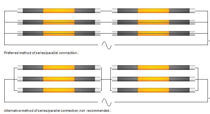
3-phase connections may include star (wye) or delta. Where a star connection is to be used, awire supply is recommended, to ensure that the phase voltages are balanced, irrespective of the phase resistances. If a 3-wire star connection must be used, then the phase resistances must always be closely matched
Matching of resistance value
It is recommended that any series connected ele- ments be selected within a resistance range of ±5% of each other, and elements connected in parallel may have a wider range of ±10%.
If any element fails or is broken after only a short period in use it can usually be replaced with a new element; preferably one from the higher end of the resistance tolerance (low amp value). If the elements have been in use for a considerable time
however, the entire group should be replaced other- wise an excessive load will fall on either the new or the old elements, resulting in premature failure.
It is good practice to divide the total number of elements in the furnace into relatively small control groups, to simplify matching at a later date. For example, a furnace fit with 48 elements, will be
far more flexible if the elements are divided into 8 groups of 6 than with 3 groups of 16 elements,
and matching of element resistances will be greatly simplified.
When a group of elements has been replaced, it is essential to ensure that the voltage output of the power supply equipment is reduced to the correct value before switching on, as overloading of ele- ments, even for a very short period, can cause irre- parable damage. The old elements may be retained for later use with others which have been in use for a similar period of time. If possible, voltage and current readings should be taken from each element before removal and the increased resistance value marked on the terminal to assist in matching at a later date.
It is important to note that the resistance values of elements at room temperature give no indication of their resistance at operating temperature and resistance measurements should always be taken at a constant temperature above 1000°C
Different types of heating elements should never be operated in the same electrical circuit, as variations in rates of resistance increase will cause overload- ing of one type or the other depending on the method of connection
Voltage reserve
To compensate for the increase in element resistance which occurs with use, a variable voltage power supply is usually provided. The amount of voltage reserve required will depend upon the elements’ rate of resistance increase and the life expected, but is usually in the order of 50 –100% of the voltage required to give full power with new elements.
For example, if 125 V is required to give full power with new elements, then a voltage range of 125 – 250 V will be required to give 100% voltage reserve, and a range of 125 – 187.5 V to give 50% reserve.
Where elements are to be operating for long periods at temperatures of about 1400°C or above, or where the furnace conditions are such that an excessively high rate of resistance increase will occur at a lower temperature, then allowance should be made for 100% voltage reserve. Con- versely, if the element temperature is very low, or the furnace only infrequently used, a voltage reserve of 50% or less may be found sufficien
Power supply equipment
A variable voltage power supply is usually pro- vided to enable the design power to be maintained throughout the life of the elements. The type of equipment used may have an effect on element performance and it is important that the correct selection procedures are adhered to if the best element life is to be obtained. Various types of power supply can be used:
1.Variable output transformer
2.Thyristor unit (SCR)
a.Phase-angle firing
b.Cycle-proportioning
3.Combined thyristor (SCR)/transformer system
Direct-on-line connectio
Generally speaking, tapped transformers provide only on-off control, unless used in combination with thyristors. Although robust, and insensitive to short term overloading, the transformer is considered to be heavy, bulky and relatively expensive in most cases.
Thyristor control offers a far more compact solution, with the option of step less variation of power, and 3-term, accurate tempera- ture control, but will require an over-rated supply, and may cause disturbance in the supply lines.
It is not usually practical to provide a voltage reserve of more than 50% using thyristor control alone, and where a large voltage reserve is required, in combi- nation with 3-term control, the best, although most expensive, option is to combine the control benefits of the thyristor, with the large voltage span of a transformer.
Thyristor control alone is common in low temper- ature furnaces, laboratory furnaces, and other equipment where the rate of change of element resistance is likely to be low.
For high temperature continuous industrial furnaces, where a large volt- age reserve is required as well as accurate tempera- ture control, then the additional costs of the com- bined transformer/thyristor system can usually be justified in terms of performance
1 Variable output transformer
Infinitely variable transformers are occasionally used to power small laboratory and experimental units but are usually too expensive for larger furnaces, where multi-tapped transformers with stepped outputs are more economic.
The maximum voltage step on a tapped transformer should never exceed 7% of the initial, full power voltage , where W is the furnace design power and R is the network resistance based on the nominal resis- tance of the elements) and the element resistance tolerance must always be taken into account when calculating the maximum secondary current ratingof the transformer
e.g. if a furnace is to be rated at 5 kW and fit with QS elements having a network resistance of 2 Ω (±15%) then the transformer spec- ification might be calculated as follows:
Nominal full power voltage = WR = 5000 × 2 = 100 V
Voltage steps must not be greater than 7% of 100 V = 7
Minimum network resistance =2 Ω -15% = 1.7 Ω
Maximum secondary current = 54 A
Minimum voltage required = 5000 × 1.7 = 92 V
Assuming that 100% voltage reserve is required then the specification could be as follows:
Input: Single-phase, to suit supply
Output: Variable from 92 V to 197 V in 15 steps of 7 V (= 4 coarse × 4 fine tappings)
Rating: 5 kVA from 92 V upwards (maximum secondary current 54 A)
1.Where a tapped transformer is to be used then an allowance should be included in the furnace design power for the reduction in power output, which will occur between tap changes. With a 7% voltage step for example, the power will fall by about 12.5% before the voltage can be adjusted to the next setting.
2.A few taps below 92 V may be included for lower powers if required.
3.If an ammeter is to be used, then it should be installed in the primary circuit where the voltage is constant; the current reading will then give a true indication of the power dissipated by the elements, irrespective of the secondary voltage setting
2Thyristor (SCR) unit
A thyristor is a semi-conductor switching device which can control the average output to the ele- ments by switching the mains supply on and off very rapidly.
Each thyristor will conduct in only one direction and for control of a.c. loads the thyristors are installed in pairs, connected in inverse parallel. The thyristors are switched by a series of pulses fed from a suitable driver unit or tempera- ture controller.
Thyristors can be simple devices, but are often pro- vided with closed loop feedback, to compensate for variations in supply voltage, load characteristics, etc.
Typical feedback modes include current control (I2 feedback), voltage control (V2 feedback) and true power control (VI feedback). In general, only V2 feedback is suitable for use with silicon carbide elements, although there are some exceptions
Current control tends to increase the power to the elements as they increase in resistance, and both power and current control can cause serious dam- age to the elements when starting from cold, when the element resistance is high.
When presented with this high load resistance, both current and power control are likely to result in the application of maximum voltage to the elements, and if the avail- able voltage is higher than the elements can with- stand, then serious damage may occur. With voltage control, the delivery of power will be controlled by the resistance/temperature characteristics of the element, starting with a relatively low power, and gradually increasing as the elements heat up.
The output characteristics of the thyristor are governed by the firing method used and the two principal types are as follows
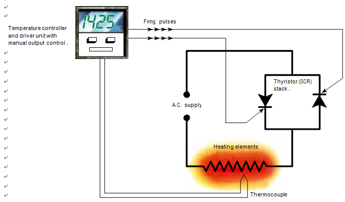
2.1 Phase-angle firing
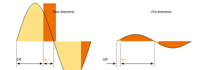
Each thyristor is triggered once in every half cycle of the a.c. supply, conduction ceasing at the end of the half cycle as the current falls to zero. In this way, the sinusoidal supply waveform is chopped, resulting in a reduction in the RMS output voltage of the thyristor stack.
For control of silicon carbide elements, a manual voltage limit control must be provided to vary the conduction angle of the thyris- tors and thus compensate for resistance increase of the elements.
Phase-angle fired units may also be fit with a current limiting device, which may protect the thyristors from accidental overload, by preventing the current output from exceeding a pre-set value, irrespective of the voltage setting.
This current limit must not be used to control the power input to the elements, as the power input (= I2R) will gradually rise with increasing element resistance, resulting in progres- sive overloading of the elements, and possible dam- age when starting from cold.
As phase-angle fired thyristors give smooth, step less control of the applied voltage, they are ideally suited for use with silicon carbide elements. How- ever, they can cause both radio frequency interfer- ence and supply waveform distortion, and consid- eration should be given to these factors when se- lecting the system to be used. The use of phase- angle firing is discouraged in many countries, or severely limited by local regulations
As there is no current flow for part of the supply cycle, phase-angle controlled loads will give rise to an apparently poor power factor, even with a purely resistive load, and this can lead to problems on large installations, especially if the firing angle is small. Generally, the starting voltage with new elements should not be less than 60% of the supply voltage, to minimize this effect.
Supply cables must be rated at the RMS current drawn by the elements (= power ÷ thyristor output voltage and not power ÷ supply voltage). This means that the power supply will be rated higher than the furnace design power, and the more voltage reserve is provided, the higher will be the required over-rating.
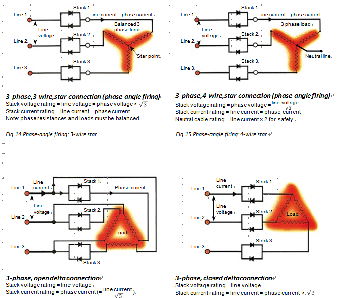
In 3-phase installations, generation of third har- monics will give rise to cumulative distortion of the supply waveform and may result in excessively high neutral currents of up to twice the line current in 3-phase, 4-wire, star-connected loads. Neutral cables must be adequately rated to carry this excess current
Although 3-wire star connection can be used to eliminate this problem, this can result in voltage imbalances between phases, espe- cially where elements are nor perfectly matched in resistance.
To minimize supply distortion in large installations, the use of a 6-wire, open-delta arrangement is recommended. The thyristors are required to carry
only the phase current and not the line current as would be required in a closed delta installation, leading to a reduction in cost, and phases can be controlled independently, leading to more flexibil- ity of control.
Calculation of the voltage output and current rat- ing of phase-angle fired thyristor units is carried out in the same way as for a transformer, taking account of the element resistance tolerance when calculating the maximum current drawn
Power monitoring – phase-angle
Most voltmeters and ammeters will not indicate a true RMS reading from phase-angle controlled
loads, and great care must be taken to ensure that the elements are not inadvertently overloaded.
Some of the digital meters currently available will respond accurately to non-sinusoidal waveforms, but the manufacturer should be consulted to ensure that a suitable instrument is supplied. True RMS, hall-effect meters, with a crest factor of 7 or above, is recommended for an accurate response
2.2 fast-cycle firing
The thyristors are triggered at the beginning of a mains cycle and remain conductive for one ormore complete cycles before being switched off for one or more cycles. This operation is continuously repeated, thus limiting the effective input to the elements. A manual control must be provided to vary the on/off ratio, and thus compensate for the gradual resistance increase of the elements.
Although the average power input to the elements may be within the normal recommended limits for start-up, temperature and atmosphere, each full cycle of the full mains voltage may cause loadings of several times this value to occur, and this can result in increased rates of resistance increase and premature, if not immediate, element failure
this reason, it is necessary to connect the elements in such a way that the element loading during full cycles of the supply voltage does not exceed15 W/cm2
To minimize the effect of the ‘on’ burst, the time base of the firing cycle must be as short as possible and preferably less than 30 cycles of a 50 Hz supply (i.e. 50% power = 15 cycles ‘on’ + 15 cycles ‘off’Slow-cycle thyristors generally have cycle times of several seconds and are not suitable for direct control of silicon carbide elements.
They may be used on the secondary side of tapped transformers how- ever, in place of conventional electro-mechanical contactors
The optimum type of burst-fired thyristor for use with silicon carbide elements is the single-cycle burst-firing type, where the required output is always reached over the minimum possible number of complete cycles (i.e. 50% power = 1 cycle ‘on’ + 1 cycle ‘off’)
The required voltage rating for the thyristors will be the same or higher than the supply voltage, but the current rating of the unit must be determined by dividing the RMS supply voltage by the mini- mum network resistance
The rating of the thyristor will therefore be much higher than that of an equivalent phase-angle fired unite
To calculate the required output from the thyris- tors, the power at the supply voltage must be cal- culated, and the on/off ratio of the thyristor limited to whatever percentage will provide the required design power.
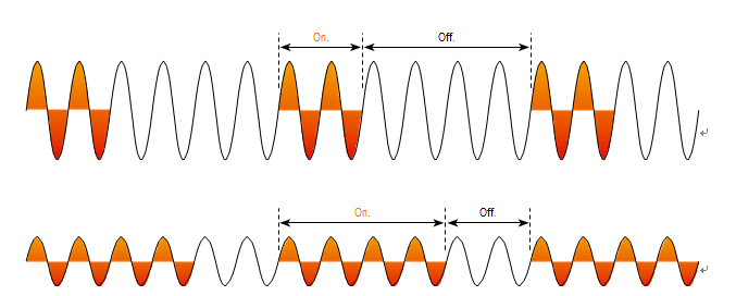

Resistive loads controlled by fast-cycle thyristors have a unity power factor and, as only full mains cycles are delivered to the load, there is no cumula- tive distortion of the mains supply. With heavy loads however, voltage drop may cause flickering lights and also affect sensitive equipment
Power monitoring – fast-cycle
It is difficult to obtain voltmeters and ammeters which will respond accurately to fast-cycle con- trolled loads, and as most meters will indicate a reading considerably less than the actual thyristor output, great care must be taken to ensure that the elements are not inadvertently overloaded. The required output settings can be calculated, as above, based on the known resistance of the ele- ments. If there is any doubt about the required setting, then the control should be set initially at a very low value and adjusted as required until sufficient power is available to raise the furnace to temperature.
The control should be left at this setting until, due to resistance increase of the ele- ments, insufficient power is available to maintain the furnace at temperature (or reach temperature if the furnace is in intermittent use). The control setting should then be increased slightly until suf- ficient power is again available
3Transformer + thyristor (SCR)
Due to the limitations imposed on the use of thyris- tor control, outlined in (A) and (B) it is sometimes not possible to provide an adequate voltage reserve, and it may be necessary to adopt a combined thyris- tor/tapped transformer power supply to ensure
an adequate element life. Thyristors can be fit on either the primary or secondary side of the transformer, although precautions are especially required for primary connection. The transformers can be fit with only 2 or 3 tappings in most cases, as the intermediate steps can be accommodated by the thyristors. If the use of a combined system is being considered, then both transformer and
thyristor manufacturers should be informed at the design stage, to ensure compatibility of the equip- ment supplied. QS can provide suggestions for the design of the equipment, on receipt of the element details, required power and temperature, and the local supply voltage
4Direct-on-line
Networks of elements may be connected directly to the mains voltage providing that the network resis- tance is sufficiently high to prevent element over- loading
The network should be designed so that the initial power output is higher than the furnace rating to provide a power reserve and compen- sate for element resistance increase. Although the capital cost of a variable voltage supply is saved by this method, only a minimal power reserve can be provided, and in addition, a larger number of ele- ments may be required in the furnace to dissipate the initial excess power.
It may be possible to gain an extra power reserve by modifying the element connections after the elements have aged (e.g. from 2 parallel branches of 3 elements in series to 3 parallel branches of 2 elements in series; or from 2 elements in series con- nected in delta to 2 elements in parallel connected in star). Because of its inherent drawbacks, direct- on-line connection is normally limited to relatively low temperature applications (under 1100°C (2010°F)) or infrequently used cyclic furnaces up to 1300°C (2370°F)
Start up procedure
Rapid heating is detrimental to all ceramic materi- als, and although Kanthal Globar SD and multi- leg elements are particularly resistant to thermal shock, care must be taken when heating up from cold to limit the applied voltage, and hence the element heating rate. The test voltage marked on every element must never be exceeded, but in general, it will be beneficial to limit the applied voltage to a lower value, calculated from the element design power, and the nominal element resistance: V= WR Where W is the design power of the element in watts, and R is the nominal element resistance
MAINTENANCE
HEATING ELEMENT MAINTENANCE RECORD
Furnace ID: _______________________
Temperature:_______________________
Atmosphere: _______________________
Number of Elements in Furnace ________
Number of Spares ___________________
SIC heating element order information:
Type:
Outside Diameter: ___________________
Heated Length: _____-______________
Overall Length: ___________________
Nominal Resistance when new:_________Ω Date Element Location Amps written On element Measured Voltage E Measured Amperage I Computed Resistance E/I Computed Watts E x I Notes Sketch of heating element layout
FACTORS THAT AFFECT heating elements SERVICE LIFE
Silicon Carbide heating elements increase in resistance during their service life. The rate at which aging occurs is affected by many factors such as element watt loading, operating temperature, atmosphere, mode of operation--continuous or intermittent and power control methods. Element life depends on many factors. The elements can last several years if operated in a favorable atmosphere at a favorable watt loading.
Watt Loading and Operating Temperature
A heating element with a higher watt loading will operate hotter, as shown on the adjacent chart. This higher temperature is directly related to the rate at which the element increases in resistance. For optimum element life, the lowest possible watt loading should be considered, in the range of 20 to 50 watts per square inch (3-8 watts per square centimeter).
Atmosphere
In clean, dry air atmosphere SG, SGR and one-piece sic elements can be operated at furnace control temperatures up to 1600ºC. The maximum element temperature is 1625ºC.The three-piece DH or U type sic elements are limited to 1425ºC. In inert atmospheres of argon or helium elements may be operated to 1700ºC.)For atmospheres containing water vapor, alkali metal vapors, flux vapors or oxygen enrichment, we recommend QS1 infusion glaze coated elements or elements of special type Please contact us for recommendations. In reducing atmospheres the maximum operating temperature is 1370ºC.
There is a protective coating of silicon dioxide on the silicon carbide. Hydrogen reduces this coating and causes the sic elements to deteriorate. Very dry or very wet hydrogen is detrimental to long service life. Nitrogen atmosphere applications are limited to 1370ºC and 30 watts per square inch (5 watts per square centimeter) maximum surface watt loading. Too high of a surface temperature will result in a silicon nitride reaction. A thermally insulative layer forms around the heating elements resulting in very high surface temperatures which damage the sic elements.
Mode of Operation
sic heating elements can be used in both continuous and intermittent operations. For maximum service life above 1300ºC. continuous operation is recommended. The reason for this is that a new element is essentially 100% pure silicon carbide with very little silicon oxide. As it is used, the silicon carbide oxidizes and forms more silicon oxide and silicon dioxide. This is what causes the element to increase in resistance over its life. The chart entitled THERMAL EXPANSION OF DIFFERENT SILICA MATERIALS show that these various forms of silica - quartz, cristobalite and tridymite have considerable size changes as they go through these phases. When the silicon dioxide in the element is cooled or cycled, it goes through several phase transformations. The high-low quartz transformation at 570ºC. involves a substantial volumetric change, which can lead to the fracture of bodies containing large amounts of quartz. As the sic elements go through these temperature ranges, the expansion and contracting of the silica can fracture the silicon carbide lattice structure which increases the electrical resistance and can cause element failure. 571ºC temperature is theoretical and the exact element temperature can vary somewhat. For these reasons, we recommend a minimum idling temperature of 704ºC, to remain well above this inversion temperature. There are those customers who feel it is more economical to conserve on energy and suffer a shorter element life. There are other customers who prefer the longer element life at the expense of the energy used during idling. Since each application is different, the choice remains with the customer.
Power Supply
The resistance of sic elements increases gradually during their useful life. Therefore, some means of maintaining the power input to the furnace at a level sufficiently high to maintain the desired temperature, is required. Historically this involved the use of mechanical contactors and multiple tap transformers with up to 16 taps to be able to adjust the voltage upwards in steps, to maintain the desired power output as the elements aged. In more recent times, the use of SCR’s (silicon controlled rectifiers, also known as thyristors) have become more popular as they are less bulky, and enable very precise control of the voltage and power input to the heating elements. To provide a large voltage reserve to enable maximum life of the element elements when designing higher temperature and more industrial furnaces, the use of a combination of step down transformers with only 3 or 4 output tappings in combination with SCRs, is the most common system today. Sic elements can be used directly on the line (fixed voltages) at temperatures up to 1300ºC. To compensate for the reduced output as the sic elements gradually age or increase in resistance, the furnace or kiln is typically initially overpowered by 25% to 50%. This type of arrangement has proven very satisfactory in many applications
TROUBLE SHOOTING
SiC heating element life is limited due to several reasons, but the major reason for failure is rarely due to faulty material or workmanship. The most common reasons for element failure, which we have seen have been due to:
Mechanical stress
Terminal holes should be aligned and straight in the refractory wall. Any binding of the heating elements can cause breakage during heat-up or operation due to expansion or movement of the furnace walls. If the elements are tight in the terminal holes or something bumps or jars the elements, they will break. Please make sure the elements can be moved north and south and east and west about 4-6mm (1/8"-3/8") with a slight force such as can be applied with a thumb and a finger pushing on a pencil. This test should be done both at room temperature and at maximum furnace operating temperature. Contact straps should be long enough so that no stresses are transferred to the elements.
Arcing
Arcing occurs when the element is powered. If an element is not free to radiate freely in all directions, the section too close to a wall will overheat, arc and fail.
Careless handling
Handling of element packages by the carriers while in transit. Handling of elements by the customer after being removed from the package.
Chemical Attack
Silicon carbide heating elements should be operated in a clean environment. Glass deposits, for example, can cause mechanical breaks. The differences in coefficients of thermal expansion causes mechanical stresses in the element structure and breakage to occur. If possible, keep excessive moisture, methane and hydrocarbon vapors out of the high-temperature zone of the furnace, where the elements are located. If moisture is unavoidable, and for more aggressive furnace atmospheres, we recommend LMA infusion glazed coated elements. Please contact us if you have any questions.
Overheating
Center the element in the chamber so no portion of the heating section is in the refractory wall. This can be done by measuring the cold end length sticking out of the furnace shell and make sure they are both equal
CHECKLIST OF INFORMATION REQUIRED TO TROUBLESHOOT SILICON CARBIDE HEATING ELEMENT PROBLEMS
Date:______________
Customer data
Customer Name:_____________ QS Contact:_______________
Contact Name:_____________ Contact email:_______________
Address:______________ Contact Phone:_______________
Product manufactured/industry:_____________
Furnace Data
Furnace builder:_________________ Furnace type:__________________
Production capacity, lb/h:__________________
Production Process:________________ Furnace Power Rating,Kw:______________
Furnace Temperature, ℃:________________ Firing Cycle:__________________
Number of Zones_________________ Time to temperature:______________
Refractory/insulation thickness:_____________ Refractory Insulation Composition:___
Diameters of holes in refractory:_____________ Ceramic Terminal Tube used, size:____
Width Height Length
Chamber/Zone dimension:_____________________________________________________
Furnace atmosphere:___________________ Is atmosphere
Hat is the atmosphere dew point?_____________ Contained in muffle:_______________
What volatiles are given off from the load during heating?____________________________
Is there any steam?____________________________
Electrical data:
Electrical orientation (Wye/Delta/Single-Phase):______ SCR Rating:_______________
Transformer Voltage taps:_________________ SCR Manufacturer:_________
Transformer Rating:__________________ Method of Control SCR:_______
Transformer Manufacturer:__________________ SSR or Contactor):___________
If SCR, what firing method is employed?(phase-angle, zero-switching and type i.e single cycle.,
Slow cycle and time base , if known):_______________________________________________
Volt(AC) Phase Hz
Main Line Power__________________ ____________ _______
Element data:
Type of element & part number:__________________ Number of elements:_______________
Element loading:_________________ Power per element, KW:_______________
Element temperature:__________________ Hot zone Length:_________________
Element dimension:__________________ Cold End Length:________________
Element Spacing(Centerline to Centerline)_________Element Spacing from chamber walls:____
Connections and installation
What orientation are the elements installed in?
(Horizontal ,Vertical ,at an Angle, etc.)___________________________________
How are the elements supported?___________________________________
Are terminal tubes/lead-in sleeves being used?____________________________________
Are the terminal holes in line with each other from one
Side of the furnace to the other ?(where application)____________________________________
Are the terminal holes free of debris?(any signs of
Condensates in the holes? ___________________________________
Are the elements being packed around with fiber at the
Ends where they pass through the refractories?)____________________________________
Are the elements still able to move freely in both linear
And radial directions(important for thermal
Expansion/contraction)____________________________________
Is there sufficient stack in the length of the aluminum
Straps so as to not transfer stress to the elements?____________________________________
Are there any signs of residues on the element cold
Ends?___________________________________
Do you know/what do you think the residues are?___________________________________ Are the elements being installed in well matched groups?_________________________________
(if unclear, we can explain and help)__________________________________
Are new and old elements being installed in the same
Connection group?__________________________________
Have the transformer trapping and/or SCR outputs been
Adjusted when replacing spent elements with new ones?_________________________________
Are the aluminum braids showing signs or oxidation
Arcing or heating up?__________________________________
Are the connection clamps loose on the ends of the elements?_____________________________
How are the elements connected in each control group?
(Please describe and/or send a sketch or connection schematic)__________________________
Element radiant protection Tube data(where applicable)
Tube material_________________ Tube dimensions(mm):________________
Type(Straight ,U,W,Inner)________________ Tube length(mm):________________
Tue orientation (Hor./Ver.)__________________ Tube loading, W/cm2:______________
Number of tube:__________________ Net power per tube,Kw:______________
TIPS FOR MAXIMUM PERFORMANCE
1. Start-up -- If a transformer is used, apply minimum voltage during start up. This is usually 70%-80% of full load voltage. Any silicon carbide element may be weakened or fractured by heat shock if excessive voltage is applied in bringing the furnace up to temperature too rapidly.
2. Replacement -- Avoid mixing new elements with old ones. Reduce the voltage to the lowest value when replacements are made. Be sure to turn off and lock out power before changing elements. Never overload elements by applying an excessive voltage to get the furnace up to operating temperature in a hurry. If the broken element is in a series connection, it is usually necessary to replace all the elements connected in the series circuit. Elements in series must be matched closely. If an element has broken after the elements in the group have increased more than 10% in resistance, the entire group of elements should be replaced. If a used element of similar resistance (one which has increased in resistance approximately the same amount as the group) is available, then it could be used as a suitable replacement
3. Watt Loading -- Don't exceed the recommended watt loadings or temperatures shown in the chart below
CALIBRATION PROCEDURE
Our heating elements are calibrated in open air by applying a voltage through them that will cause them to dissipat approximately 15.5 watts/cm2 (100 watts/in2 ). The sic heating elements are calibrated in amperes rather than ohms, for it is a more convenient unit to use.
Experience shows that a sic element when being calibrated in open air at a loading of 15.5 watts/sq. cm (100 watts/sq. inch) will come to a surface temperature of 1073ºC (1960ºF) in anywhere from three to eight minutes, depending upon the size of the Sic element.
Then, current will drop slightly and another two or three minutes is required before the element becomes stable at a temperature of approximately 1073ºC (1960ºF). If the element that are calibrated in free air are placed in an enclosure or in a semi-enclosure backed by a reflector, the ambient temperature will rise above that of the surrounding room with the result that the resistance of the element will be affected. It is possible to check the ampere rating of an element while it is at temperature in the furnace.
A clamp-on ammeter is required and readings are taken by clamping around the aluminum braided terminal strap. The value is a comparative figure which can be used to relate other elements in the furnace or other elements measured with the same method. To compute the resistance, measure the voltage drop across each element, then divide the voltage by the current. This will give you the resistance in ohms of the element. It is possible to calibrate used elements on a higher voltage than was originally used, the advantage being a higher voltage will make it easier to detect any unevenness in resistance or to detect any defects or nonuniformities that might have developed during the operation of the elements.
If used elements are calibrated on the same voltage as new elements, the elements will not have the same surface temperature because they have increased in resistance, but if the elements are matched in this manner they will still be very close to being matched at a higher voltage.
If you elect to calibrate used elements at a higher voltage, the simplest way to select a voltage for recalibration is to multiply the initial nominal resistance of the element by the estimate of the increase in resistance.
If you had an element that had doubled in resistance multiply the nominal resistance by two.
If the element has tripled in resistance, multiply the nominal resistance by three.
The recalibration voltage can be determined by using the equation E=√WR. Where W equals the surface area of the element (square centimeters or square inches) times 15.5 (watt/cm2 ) or 100 (watts/in2 ) and R is the used element resistance.
The crayoned markings on the element indicate the calibration amperage, month and year the Sic heating elements was manufactured.
Holding the heating elements so that the markings are right side up and reading from left to right, the first letter indicates the month.
The letter A through L appear in this space (A is for January, B for February, etc.).
The second is a number 0 through 9. This is the year the sic heating elements was manufactured .
The next mark on the sic heating elements would appear near the other end and will be the calibrated amperage.
CALIBRATION PROCEDURE
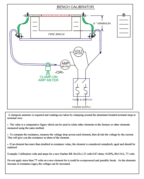

 martin@qs-heatingelements.com

