Generation discripation.
The MoSi2 element is a dense cermet material consisting of molybdenum disilicide (MoSi2) and a glassy phase silicon dioxide (SiO2). The element is a resistance type heating element that converts electrical energy to heat energy . MoSi2 heating elements are characterized by good heat and electrical conductivity.
They have low thermal expansion and withstand corrosion and oxidation. all characterized by long life and consistent performance. element temperatures up to 1850°C (3360°F)
The elements are most frequently used suspended with the bottom of the hot down. The element consists of two cold ends (Lu) . The cold ends are twice the diameter of the hot section and are attached by a weld. The extremities of the cold ends are metallized with aluminum to provide a low-resistance contact surface to which the electrical connections are made with flat braided aluminum straps the elements are available as straight or bent elements in a wide range of shapes and sizes, .
Unique Properties
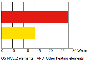
1.Higher watt loadings compared to other heating solutions up to 1850ºC in oxidizing atmospheres 30 W/cm2 compared to 15 W/cm2
2. Longer life and Corrosion resistance when cycling at high temperatures and. in reactive atmospheres and all reduced ,oxygen deficient atmospheres..
3. Fast ramping. Can be used continuously or intermittently. New and old elements can be connected in series
4. ease of replacing failed elements . High power concentration may be applied
5. High purity material .Thinner glaze layer. Improved form stability
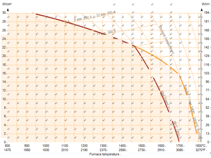
7.comparison of surface loading.
Grades
MoSi2 heating elements includes three grades with specific features for use in demanding applications and atmospheres, including nitrogen, hydrogen, vacuum and mixtures of endogas and reducing atmospheres.
Grade 1700°C.
Good heat and electrical conductivity. Low thermal expansion. Withstand corrosion and oxidation.and the other is Specially designed for working in nitrogen. offers long life at high temperatures in all reducing and oxygen deficient atmospheres.
Dedicated heating element for semiconductor
1. this product is precision maching with highter power and it can provide uniform thermal field for electric furnace
2. corresponding shapes can be manufactured based on operating requirement of customers this product can maintain a certain performance in use with long service life.
3. comparing with the metal wire it can bear greater surface load and rapid temperature increasing system(fast cooling and temperature increasing)
4.it can match with various dimensions of wafers from small size to large size namely multi-application.
5.it can ensure the elements of relevant equipment if being used under high temperature
electric furnaces for semiconductor wafers cylinder -shaped electric furnaces
Max. temperature 1700°C
Grade 1800°C.
Good heat and electrical conductivity. Low thermal expansion. Withstand corrosion and oxidation with better hot strength and form stability.and one is designed to meet the demands for clean process heating in the research and electronics industries the other is designed for a longer life of small dimension elements in temperature cycling condition with better hot strength and form stability.
Delicated heating element for TTO
1.it is specially designed for TTO electric furnace and it can bear greater surface load
2.the product has high purity and the impurity content is reduced to the utmost extent so as to ensure the cleanness of electric furnace
3.the junction state between the heating element protective layer and element matrix surface is improved through special treatment so that the protective film is not easy to fall off when using the heating element
4.the junction stale between the heating element productive layer and element matrix surface is very good so that it is very suitable
for high oxidizing gas atmosphere furnaces
5. good high temperature strength and low defomationprobability
ITO target material sintering electric furnaces
Max. temperature1800°C
Grade 1850°C
. Good heat and electrical conductivity. Low thermal expansion. Withstand corrosion and oxidation and has higher purity and a surface with better adhesion
Delicated heating element for dental furnace
1.the heating element has high purity which can reduce the impurity content to the utmost extent
2.the product has good high temperature strength which can be bear greater surface load under high temperature
3.the product can adapt to electric furnaces with frequent use and fast temperature increasing and decreasing
4. the protective layer of heating elements is h=thin and compact which can avoid it from falling off during using to a large extent
precise electric furnaces having highter requirement on heating elements such as electric furnaces for dentistry
electric furnace with fast temperature inceasing and decreasing frequent use and short sintering period
Max. temperature1850°C
Special Shapes are also available….
QS MoSi2 heating elements , Half Cylinders, and Flat Panel Heaters The module consists of a high temperature ceramic fiber cylinder and a molybdenum disilicide heating element.
The molybdenum disilicide is the same material we use for the U shaped heating element. The heating element is in contact with the fiber therefore the temperature of the element is limited to 1600ºC. The highest practical muffle furnace temperature is 1550ºC. The heating module makes a neat little muffle furnace capable of rapid heat up, accurate temperature control and uniform temperatures. The module comes assembled in various diameters and lengths. The most popular shaped module has the MoSi2 element spirally wound, set in grooves, and stapled in the internal diameter inside the fiber cylinder. When it is desirable to open the furnace or muffle in two halves along the muffle axis, the heating module is supplied in half cylinders. On half cylinders the heating elements are formed into continuous hairpins (U-shaped).
The MoSi2 material is stapled to the fiber module. Both types of heating modules can be used with the axis of the muffle horizontal or vertical. For the half cylinder modules, a different staple arrangement is necessary therefore the operating position must be specific when ordering the module.
SHAPE
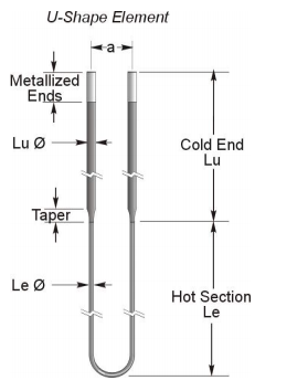
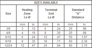
Size available.
Custom configurations
In addition to MoSi2 elements in standard shapes and sizes we provide special designed MoSi2 elements according to customer needs, enabling an optimized element design for each particular application
The mechanical and physical properties |
| 1700℃ | 1800℃ | 1850℃ |
Tensile strenght at 1550℃ | | 100 MPa±25% | 100 MPa±25% |
Bending strenght at 20℃ | 450 MPa±25% | 450 MPa±25% | 300-400 MPa±25% |
Compression strenght at 20℃ | 1400-1500 MPa | 1400-1500 MPa | 1400-1500 MPa |
Fracture toughness,KIC,at 20℃ | 3-4 MPam1/2 | 3-4 MPam1/2 | 4 MPam1/2 |
Hardness, HV, at 20℃ | 9 GPa | 9 Gpa | 8 GPa |
Density | 5.6 g/cm2 0.20lb/in2 | 6.5 g/cm2 0.23lb/in2 | 7.0 g/cm2 0.25lb/in2 |
Porosity | < 5% | < 1% | < 1% |
Thermal conductivity 20-600℃
600-1200℃ | 30WM-1K-1
15WM-1K-1 | 30WM-1K-1
15WM-1K-1 | 30WM-1K-1
15WM-1K-1 |
Coefficient of linerar expansion | 7-8 X 10⁻⁶K-1 | 7-8 X 10⁻⁶K-1 | 7-8 X 10⁻⁶K-1 |
Specific heat capacity at 20℃ | 0.42 KJ kg-1K-1 | 0.42 KJ kg-1K-1 | 0.42 KJ kg-1K-1 |
Emissivity | 0.75-0.85 | 0.70-0.80 | 0.70-0.80 |
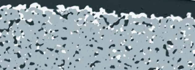
Microstructure of a QS MoSi2 element. Grey = MoSi2 , white = Mo5Si3 , dark = SiO2
Operation temperatures
Maximum recommended element temperature in atmospheres |
Atmosphere | Grade 1700℃ | Grade 1800℃ | Grade 1850℃ |
Air | 1700℃ | 1800℃ | 1850℃ |
Nitrogen | 1600℃ | 1700℃ | 1800℃ |
Argon, helium | 1600℃ | 1700℃ | 1800℃ |
| | | |
Dry Hydrogen, dewpoint-80# | 1150℃ | 1150℃ | 1150℃ |
Moist Hydrogen , dewpoint 20# | 1450℃ | 1450℃ | 1450℃ |
Exogas(e.g. 10%CO2,5%CO,15H2 ) | 1600℃ | 1700℃ | 1800℃ |
| | | |
Exogas(e.g. 40% H2,20% CO) | 1400℃ | 1450℃ | 1550℃ |
Cracked and partially burnt ammonia(≈8%H2) | 1400℃ | 1450℃ | 1550℃ |
DELIVERY
Most sizes and types can be shipped 3 to 4weeks after receipt of an order. Emergency shipments for smaller quantities can usually be made in 2 to 3 days
Ordering
The following information is required:
Quantity Required:
Hot Zone/Cold End Diameter: 3/6, 4/9, 6/12, 9/18 or 12/24:
Hot zone length – Le:
Cold end length – Lu (includes taper):
On-center distance between legs:
Operating temperature of furnace:
Grade :
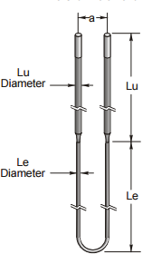
information normally required to make molybdenum disilicide element recommendations
describe furnace or kiln:
describe process:
normal operating temp.
maximum design temp
. atmosphere:
operation: continuous - or - batch firing cycle:
heat up time to temp:
soak time @ temperature:
please provide dimensioned sketch for load, hot chamber and door location load dimension: (length x width x height):
hot chamber dimension (length x width x height):
wall thickness and composition: temperature uniformity required:
will atmosphere be contained in muffle?
muffle composition: if continuous, how is material transported through kiln?
weight of material to be heated per hour will any volatiles be given off during firing?
estimated power required kw/hr:
ncoming voltage:
maximum amps available:
single phase or three phase:
method of power control, zero cross scr, phase angle? how many zones of temperature control?
is multiple tap transformer available?
rated kw: 1 or 3 phase maximum secondary amperes & voltage taps
Permissible Atmospheres
Molybdenum disilicide heating elements are designed particularly for use in oxidizing atmospheres, i.e., those containing oxygen. Neutral atmospheres such as nitrogen and rare gases as well as CO and CO2, can be harmful to Molybdenum disilicide elements. Maximum element surface temperatures in various gases are shown in the table above.
Reducing atmospheres attack the protective layer and therefore lower permissible maximum use temperature
Air
Silicon and molybdenum can oxidize at approximately 550ºC (1020ºF). The reaction product is a yellow powder called “pest”. Such “pesting” is normally innocuous since it is merely a surface phenomenon.
Since both H2O and CO2 are oxidizing, their presence in a furnace atmosphere is beneficial, elevating maximum temperature.
Exogas
This atmosphere typically comprises 10% CO2, 5% CO, 15% H2 and the balance N2. This atmosphere is considered oxidizing with respect to Molybdenum disilicide.
Endogas
This atmosphere typically comprises 20% CO, 40% H2 and the balance N2. The Maximum use temperature will be determined by dewpoint and gas velocity.
Carburizing atmosphere
Molybdenum disilicide elements are not attacked by the atmosphere in a Carburizing furnace. If carbon builds up in this type of furnace it should be removed by periodic firing in oxidizing conditions
Nitrogen atmosphere
Nitrogen in a furnace atmosphere is typically used for nitration of ceramics, as a protective gas, or to balance the furnace atmosphere.
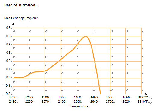
Nitration of ceramics is normally carried out at 1250-1550ºC. If the protective glaze coating on the element were degraded, nitrogen could react with the MoSi2 on the element surface to form silicon nitride (Si3 N4) which would scale off to damage the element. When operating below 1250ºC (2280ºF) element temperature the reaction is minor. However, above 1500ºC (2920ºF) up to 1700-1800ºC (3090-3270ºF) element performance is dependent on the dewpoint and time at temperature.
In cyclic conditions, the oxide layer on the elements can be restored by operating for a short time in air at 1500ºC. When operating for extended periods at temperature (continuous furnaces), the actual formation of a thin layer of Si3 N4 at the surface of the elements offers the best protection against further gaseous reaction. The element’s protective glaze can be restored in the furnace where the elements are installed, by operating them in air above 1550ºC (2820ºF) for a couple of hours. I Squared R offers pre-glazed elements for use in Nitrogen atmospheres.
Nitrogen and Hydrogen
Any mixture of these gases should be treated similarly to hydrogen.
Hydrogen
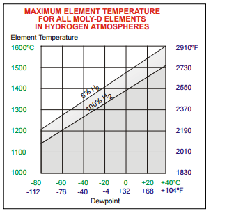
The effect of hydrogen is significant. Dry hydrogen can reduce SiO2 and MoSi2 to form silicon and silicides with lower silicon content. Reaction rate varies directly with temperature and inversely with dew point.
Floride and Chlorine
MoSi2 is attacked severely by halogens even at low temperatures. They can occur as pyrolysis products of charge contaminants
Vacuum
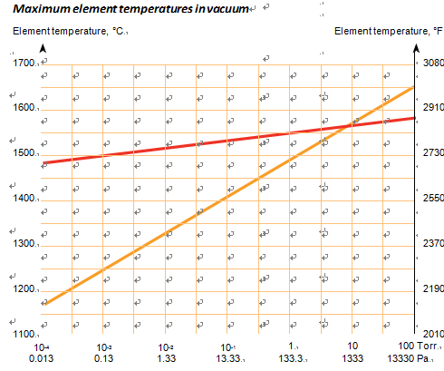
Molybdenum disilicide elements are not intended for use in a high vacuum at high temperatures. The adjacent graph gives maximum element surface temperature as a function of furnace atmospheric pressure.
Metals
All metals react with MoSi2 at high temperatures to form silicides. Since dust from metal will react with the element’s protective glaze it is recommended the Molybdenum disilicide element be protected from metal splashes and fumes.
Alkali
Metal oxides and salts act as a fluxing agent and react with the protective glaze on the elements. Since castable furnace linings contain alkalis, their selection for high temperature (1550-1600ºC) furnaces is critical, and should not be used beyond this temperature.
Ceramics
If element supports are used, element temperature should not exceed 1600ºC to prevent reaction with the support. Suitable support materials are mullite and sillimanite. In firing of ceramics, decomposition products of organic materials - binders, plasticizers, ect.- must be removed to prevent element contamination at high temperatures.
Glass
MoSi2 elements are generally well-suited to glass melting furnaces.
. TECHNICAL INFORMATION
RESISTANCE CHARACTERISTICS
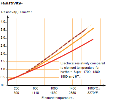
The MoSi2 heating element is a resistant type heater that converts electrical energy to heat energy . Molybdenum disilicide increases in resistance by a factor of approximately 10 between 20ºC and 1800ºC. See graph .
MAXIMUM AMPERES
The Molybdenum disilicide elements are low-voltage high-current elements. Below is the maximum recommended current for each standard hot zone diameter. The hot zones can take more power but the cold ends tend to over heat and cause strap and clamp failure.
Maximum Recommended Amperes |
Hot Zone
Diameter in mm | 3 | 4 | 6 | 9 | 12 |
|
Current Amperes | 75 | 115 | 200 | 365 | 560 |
oxide growth
The oxide growth at cer- tain temperature as function of time have a parabolic growth. The growth of the oxide layer, the glaze, is much reduced, compared to other elements see diagram below. A thin oxide layer results in a much-improved service life, because the tension is reduced between the base material and the surrounding oxide, depending on the different thermal expansion coefficien
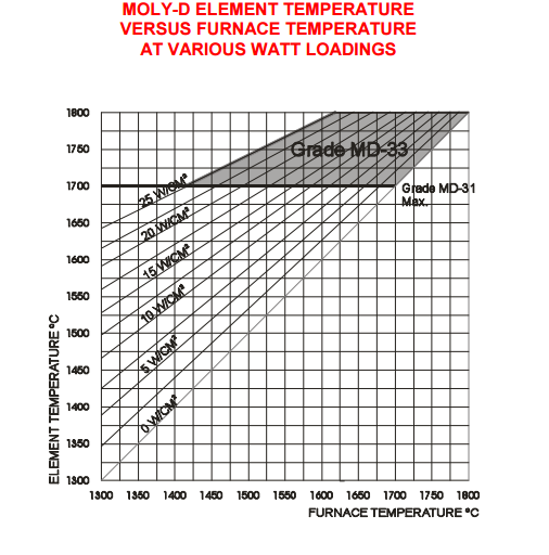
Element temperature .furnace temperature .watt loading.
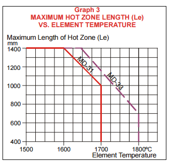
APPLICATIONS
The QS MoSi2 program offer is based on a wide range of high temperatures applications. Here we present the largest segment with typical processes. We offer infinite options due to our customized de- signs where demands on high temperature solutions are needed. Our products are best used by custom- ers looking for energy savings, economic benefits, increased productivity and low maintenance.
GLASS
The QS program includes products for the manufacture of many types of glass, such as float glass (flat glass), fiber glass, technical, specialty and fiber glass, glass containers, glass tubing and art glass. Our products are widely used in, for example:
Annealing lehrs
Danner process / Velo process (glass tubes)
Float baths (tin baths)
Glass ampoule sealing (pharmaceutical)
Glass fusion / downdraw process (display glass)
Glass feeders (forehearths)
Glass cullet melting (fiberglass)
Glass toughening furnaces
Glass bending furnaces (e.g. windshields)
Glass drawing furnaces (single fiber)
Pot furnaces (open, closed and scalped)
Here are two typical glass processes:
Glass forehearth (feeders)
—Glass fusions/downdraw process
CERAMICS
The QS program includes three products for the production of traditional ceramics, functional ceramics and ceramics used as engineering materials. For example, our products are widely used in:
Casting of ceramics
Ceramics sintering
Ceramics firing
Ceramics coating
Heat treatment of ceramics
Firing and glazing of tableware
Firing of refractories
ALUMINIUM
The QS program includes a wide range of products for primary aluminium production and secondary aluminium processing. For example, our products are widely used in the following applications:
Primary aluminium production
Rodding shops
Cast houses
ladle drying, ladle pre-heating and ladle holding
anode yoke pre-heating
anode stub drying
cathode pre-heating
filter heating
Secondary aluminium processing
Aluminium casting
Aluminium rolling
Aluminium extrusion
SEMICONDUCTORS
The QS program includes diffusion cassettes for the manufacturing of crystalline silicon wafers for semiconductors.
QS diffusion cassettes cover a wide range of processes, such as:
Fast-cooling processes
Oxidation processes
Nitriding processes
HEAT TREATMENT
The QS MoSi2 program includes products for different types of heat treatment processes for steel, aluminium and other metallic materials. Our products are widely used in, for example:
—Annealing furnaces
—Carburizing furnaces
—Galvanizing furnaces
—Hardening furnaces
—Sintering furnaces
ELECTRONIC INDUSTRY
The QS MoSi2 program offers products for the heating processes in the electronic industry. Our products are used in, for example:
—Furnace for single growth crystal Si,GaAs
—Diffusion cassettes
—MLCC sintering
ITO sintering
all types of clean processes in the research- and electronics industries.
FURNACES
We offer products for both electrically heated furnaces . Our products suit, for example:
Dental furnaces
Diffusion furnaces
Enamelling furnaces
Heat treatment furnaces
Dental zirconia sintering furnaces
Rapid Sintering Furnaces
Ceramic sintering furnaces:
Gem enhancement firing
Float process for fused silica
Sintering furnace
Reducing and oxidizing furnace
Diffusion furnace for semi-conductor industry
laboratory and high- temperature process furnaces
Boggie hearth furnaces
Car bottom furnaces
Chamber furnace
Conveyor furnace
Crucible furnaces
Roller hearth furnaces
Rotary hearth furnaces
Shaft furnaces (batch type furnaces)
Tilting furnaces
Top head furnaces (hood kilns)
Walking beam furnaces
Shaker hearth furnaces
Pusher furnace (continuous type furnaces)

Installation Instructions
1.) Carefully unpack the MoSi2 elements from the packaging material in the master carton. Several individual cartons (5 or 6) will be taped together in the master carton. Lift the bundle out of the master carton and lay it on a table or flat surface.
2.) Cut the tape holding the individual cartons together and lay each individual carton flat on the table, with the chip box edge up. Cut the tape and allow the chip box to open. Carefully remove the two or three layers of foam exposing the individual element.
3.) When unpacking individual elements care should be taken to avoid any bending or twisting of the element. DO NOT squeeze the aluminum sprayed ends together.
4.) Place the element horizontally on a table and insert the terminal ends in the passage brick ensuring that the correct length of terminal ends are protruding from the top of the brick. Do not remove the wooden spacer until the terminal ends have been inserted in the brick. Then remove the spacer. Be careful not to scratch the glaze coating on the Lu section.
5.) Pack the appropriate grade ceramic fiber loosely into the terminal holes approximately .5" to 1" in from the cold face. DO NOT pack too tightly; allow for expansion. This packing is only to prevent heat from chimneying out attacking the terminal straps.
6.) Attach the element holders to each terminal leg and tighten in place. Be sure each leg has the same dimension from the top of the holder to the end of the leg. Be careful not to twist or bend the element during this process. When determining the position of the element holder it is critical that the tapered section between the heating section and the terminal end be completely below the hot face of the lining. If any part of the tapered section is in the refractory lining it may overheat causing element failure or refractory damage.
7.) Connect the aluminum braided strap to the terminal ends of the element. Do not bend or twist the element during this procedure. Be sure to connect the strap to the element before attaching the strap to the bus bar.
8.) The element is now ready for installation into the furnace.
9.) Once the element is positioned in the furnace, connect the terminal strap to the bus bar. Do not pack insulating material in the terminal compartment (over the braid) or the braid will get too hot and fail.
10.) Now check the element to be sure it is free to expand and contract on heating.
11.) Turn the power on to the elements and bring them up to temperature. To grow the protective glaze on the elements, the elements should be raised to a temperature of 1200ºC and operated at this temperature for about 15 minutes. The 1200ºC should be obtained in 1 to 3 minutes. The furnace does not have to reach temperature, only the elements. This can be accomplished with the door open or closed. We caution that the amperes through individual elements not be exceeded, 3/6--75 amps, 4/9-- 115 amps, 6/12--200 amps, 9/18--365 amps, 12/24--560 amps. 12.) After the initial heat up, turn the power off and check that both the element holders and the braid connections are tight. Sometimes expansion takes place on heating, resulting in loose connections. Be sure the element has not slipped or cocked in the terminal holes, by checking that both terminal ends are equal.
Necessary distances
distance to wall
It is important that the distance between wall and heat- ing zone of the element is large enough to avoid contact. In the case of long elements at high temperatures, electro- magnetic forces and bad centering when installing the elements may cause the elements to come in contact with the walls, causing damage.
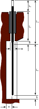
The minimum distance, e, between the heating zone of the element and the furnace walls depends on the length of the element (see the figures to the right).
When installed along the wall it is:
For Le < 1000 mm (39.4 in); e = Le /20
For Le < 300 mm; e = min. 15 mm (0.6 in)
For Le > 1000 mm (39.4 in); e = min. 50 mm (1.97 in)
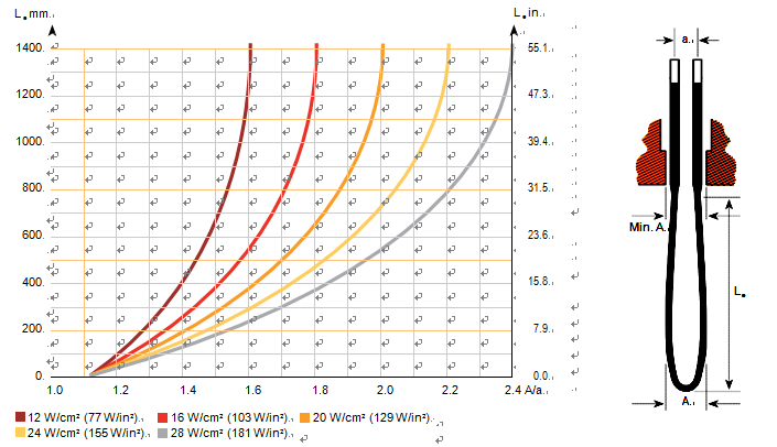
When installed perpendicular to the wall, the deformation due to the electromagnetic forces must also be consid- ered. The reason is that the deformation causes reduc- tion of the distance between part of the heating zone and the wall. After calculating the magnitude of deformation (see the figure on page 12 “Deformation of Kanthal® Super elements”), the distance E can be calculated and
e is estimated in the same way as for elements installed parallel to the wall.
A – a
Emin = e +
2

distance to bottom
In order to prevent the elements from coming into contact with any material deposited on the bottom of the furnace and to compensate for the elongation of the elements at high temperatures, the recommended vertical distance h between the element bend and the furnace floor should be at least:
h ≥ Le ; min. 10 mm 20
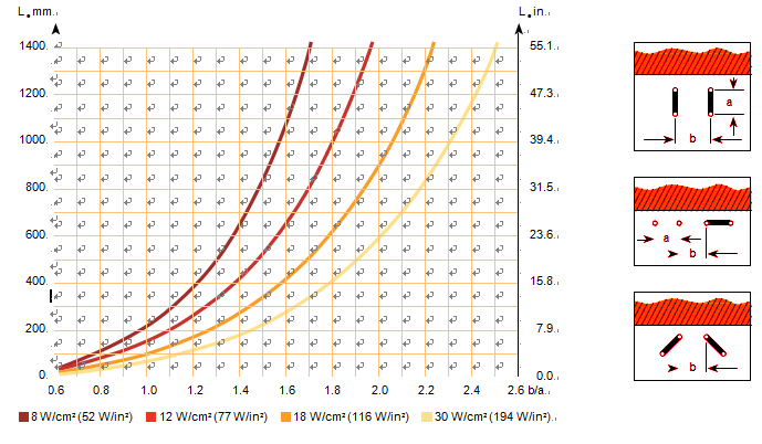
Distance between elements
Minimum distances, b, between adjacent elements are given in the figure on the below page “Necessary distances”.
necessary distance,b,to counteract the effect of the electromagnetic force on QS elements
Deformation of QS elements due to electromagnetic forces,valid for all sizes
Important istallation parameters for passage brick and skewbrick |
Element size | 3/6 | 4/9 | 6/12 | 9/18 | 12/24 |
| mm | in | mm | in | mm | in | mm | in | mm | in |
Hole diameter of passage brick | 9 | 0.35 | 12 | 0.5 | 15 | 0.6 | 23 | 0.9 | 30 | 1.2 |
Recommended min. width of opening in skew brick, w | 15 | 0.6 | 20 | 0.8 | 25 | 1 | 30 | 1.2 | 40 | 1.6 |
The minimum length of opening A is calculated according to the diagram above |
Vertically mounted elements
The exceptional properties of QS MoSi2 elements can best be utilized when the elements freely radiate in the furnace chamber.
U-shaped elements fitted through the furnace roof and vertically suspended in the furnace should be considered as the standard design for a QS MoSi2 furnace . The elements are normally placed along the side walls, but in wide furnaces it may be necessary to place elements across the width of the furnace to provide the power required.
Certain furnace designs do not permit elements to be fit- ted through the roof. The internal height of the furnace may be such that more than one level of elements must be installed. In these cases elements with bent terminals or heating zones are available .
Horizontally mounted elements
In some types of furnaces where the roof height is low, horizontally installed QS MoSi2 elements may be the most economical and efficient alternative.
As QS MoSi2 elements start to soften at tempera- tures around 1200°C , they must generally be supported when used horizontally. This limits their maximum operating temperature because of possible reactions with the supporting material. If a reaction occurs between the silica layer on the element and the supporting brick, the element may adhere to the brick and fracture when cooling down. Even when suitable dense bricks of sillimanite or mullite type are used, the maximum element temperature must not exceed 1600°C (2910°F). Sillimanite or mullite grains (≈ 3 mm/0.12 in) can be used on the supporting surface where applicable.
Brick lined furnaces
To facilitate the installation of QS MoSi2 elements in brick lined furnaces, passage bricks are used. They are installed in openings in the roof or side wall (fig. 1 and 2). The passage bricks mounted through the roof often rests on a skew brick, which has oval holes for the elements. The passage bricks are made of heavy duty insulating firebrick of a quality matched to the furnace temperature.
Ceramic fiber lined furnaces.
In fiber lined industrial furnaces, e.g. forging furnaces, if passage plugs of fiber or refractory bricks are used, then the complete element assembly also needs to be sup- ported by the furnace roof or side walls.
In small fiber lined furnaces, e.g. laboratory furnaces, it may be sufficient to introduce the Kanthal Super ele- ments through slots in the insulation and fill the space around and between the terminals with loose ceramic fiber .
In furnaces for temperatures above 1700°C (3090°F), it is important to relieve the hot face lining of the roof from the weight of the element assembly. It is recom- mended to use a divided passage plug of ceramic fiber or a passage plug supported by the cold side of the roof
The weight of the element sets is carried by the outer lining. Especially useful in furnaces for very high temperatures.
Furnace operation
initial start-up procedure recommendations
•Review the installation instructions of the furnace to verify that it is in operating condition.
•Become familiar with the various adjustments on the controller or programmer before operating the furnace for the first time.
•Do not leave the furnace unattended during the initial break-in period.
•Check the current limit of the power controller. Gen- erally the current limit is pre adjusted before shipping.
•Note that fibrous insulation is fragile and that the QS MoSi2 heating elements are also subject to breakage if handled improperly. Take special care with all furnace components at all times.
Starting up a newly-bullt furnace
When starting up a furnace for the first time or after it has been relined, it is necessary to dry it out so that the lining is not damaged. This is especially important when the furnace is brick lined. As far as the QS MoSi2 elements are concerned, the quicker the furnace can be brought up to full operating temperature, the better. The elements may also be attacked by gases and dust given off from the lining during the first firing of a furnace.
It is therefore very important to ventilate the furnace thoroughly during the drying-out process.
We recommend the following procedure as suitable for starting most QS MoSi2 furnaces.
Step-down transformer and on/off control
Open the furnace door slightly and switch on the start- ing voltage (1/3 or 1/4 of operating voltage) for the first drying-out period at 100 – 200°C (210 – 390°F).
Switch over to an intermediate voltage (2/3 or 1/2 of operating voltage). This must be done quickly in order to avoid too much reduction in element temperature and the resulting high current surges which may cause damage.
Allow the furnace door to remain slightly open for ventilation to continue while the furnace temperature rises gradually to 800°C (1470°F). When the furnace has reached this temperature, close the furnace door and al- low the furnace to run up to full temperature at operat- ing voltage.
hyristor control
When thyristor control is used, the remarks regarding operating voltage do not apply. It is advisable to reduce the current limit during the drying-out period. Other- wise, the same considerations apply as with a furnace with step-down transformer and on/off control.
For QS MoSi2elements it is advantageous if they are allowed to work at an element temperature of at least 1500°C (2730°F) for one half to one hour as part of the initial start-up procedure.
Naturally, these basic instructions are not applicable to all furnaces. On large furnaces it is often advisable to dry out the brickwork by means of a separate source of heat before installing the QS MoSi2 elements.
Replacement of elements
One of the greatest advantages of QS MoSi2 ele- ments is that a defective element can easily be replaced without the furnace having to be cooled down. Vertically mounted elements are replaced as follows:
After having located the defective element, unbolt the contacts from the busbars and remove the ceramic fiber around the upper part of the passage brick, after which the element and the passage brick may be lifted out. A previously assembled unit consisting of a new element complete with passage brick and element holders now should be inserted through the hole in the furnace roof.
The contacts which have been removed from the dam- aged element can be used again providing that they are undamaged. If the contact surfaces are oxidized or dam- aged to such an extent that they cannot be restored to a serviceable condition, they should be replaced
temperature control
The type of thermocouple used for temperature control depends on the furnace temperature. Type K has good stability to 1200°C (2190°F) and can be used in many heat treating furnaces. Temperature measuring above 1200°C (2190°F) is usually performed with thermocou- ples made of platinum-platinum/rhodium.
Thermocouples age faster the higher the furnace temper- ature is. In Pt-Pt/Rh thermocouples there is a structural change in the platinum and diffusion of rhodium occurs at the junction. Problems with temperature corrosion and overheated QS MoSi2 elements are often related to ageing thermocouples.
By alloying the platinum with rhodium the usable temperature increases. A high content of rhodium in both shanks gives the highest permissible furnace temperature. When the rhodium content is increased, the EMF (electromotive force) decreases and this affects the accuracy of the measurement. When thermocouples are utilized at the maximum classifying temperatures,
it is important to check the EMF frequently in order to avoid increased furnace temperature due to the age- ing. In high temperature furnaces with QS elements operating at furnace temperatures above 1750°C (3180°F), using Pt/20% Rh - Pt/40% Rh, it has been found that the EMF can have decreased signifi- cantly after only 4 – 5 hours at furnace temperature.
By the time this has occurred, the thermocouple has become more stable and the change is slower with time. This thermocouple has a low thermoelectric output and small changes can lead to large variations in the furnace temperature and element temperature with subsequent element problems.
For high temperature furnaces we recommend two ther- mocouple positions close to each other in the roof. One thermocouple for the controller and the SCR, the other to check the operating thermocouple and the actual fur- nace temperature. It is important that the thermocouple for checking is exposed to the furnace temperature only when the checks are being carried out.
Standard platinum-platinum/rhodium thermocouples |
| max. service temperature |
Continuous | Intermittent |
℃ | ℃ | ℃ | ℃ |
Pt/Pt 10 Rh, Type S | 1400 | 2550 | 1650 | 3000 |
Pt/Pt 13 Rh, Type R | 1400 | 2550 | 1650 | 3000 |
Pt 6 Rh/Pt 30 Rh, Type B | 1500 | 2730 | 1800 | 3270 |
Pt 20 Rh/Pt 40 Rh | 1600 | 2910 | 1800 | 3270 |
safety precautions
Use dark glasses when observing glowing QS MoSi2 elements. The eyes are subjected to great strain when observing tempera- tures above 1400°C (2550°F).
QS MoSi2 elements which have been operating for a long time at high temperature and have then cooled down sometimes have internal stresses which cause the glaze to splinter into small frag- ments.There have been instances where elements which have been cold for several days have emitted a shower of fine glaze particles when touched.
Power Control, power supply and wiring
Material Characteristics
QS MoSi2 ELLMENT has two basic material properties that call for special attention when designing the control system.
1.The resistivity increases steeply with temperature . The resistance of an element at 20°C is about 11 times lower than the resistance of the same element at 1500°C (2730°F). Hence, if full voltage is applied when start- ing, a peak current of 11 times the nominal current will flow through the element. This would cause fuse blowing or thyristor failure.
2.The material is brittle at low temperature which means that excessive amperage may cause electromagnetic forces large enough to fracture the element.
Control in general
The low cold resistivity of QS heating element implies that full operational voltage cannot be applied to a cold furnace.
In the past, only tapped transformers were available, al- lowing a reduced voltage to be applied when the furnace was cold, and then the voltage was gradually increased as the elements heated up, thus maintaining currents within manageable levels
With the advent of modern thyristor (SCR) power control units and the various feedback control features available today, we now have a reasonably economical and reliable means of limiting the start-up currents and taking full advantage of the rapid heat-up capability of Kanthal Super
Today furnaces equipped with Kanthal Super elements are controlled in the following ways
thyristor control
1.Phase-angle fired thyristors with or without a transformer.
Burst fired thyristors with phase-angle start with or without a transformer
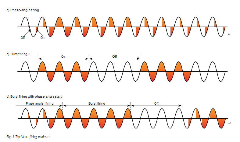
thyriStor Control
Phase-angle firing
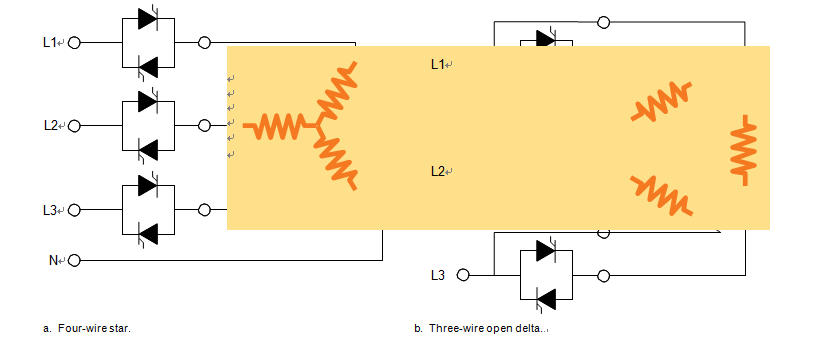
In phase-angle firing the power is controlled by allowing the thyristors to conduct for a part of the AC cycle only (see fig. 1a). The thyristor should have a current ramp turn on function and a RMS (root mean square) current limit facility. It should be noted that this is not the same as the ramp function of the temperature controller.
The thyristor starts to conduct with a small conduction angle and then it increases towards maximum conduc- tion during a number of periods. The more power needed, the larger part of the sinusoid is allowed to pass through the thyristors. If maximum permitted current is attained before full wave, the current limit facility does not permit further increase of the conduction angle.
It is essential that the current is both measured and limited in the RMS method. The reason for this is that in phase-angle firing, one is working with distorted current wave forms, and then the RMS method of current mea- suring is the only way to obtain a correct and meaning- ful value.
The ramp turn on function is required for the thyristor to work properly and gives the current limit function time to work.
The main disadvantage of phase-angle firing is that it generates radio frequency interference that may cause malfunction in sensitive electronic equipment
In burst firing the power is controlled by allowing the thyristors to be conductive for one or more complete cycles and then non-conductive for one or more cycles. The higher the power needed, the more conductive cycles and the fewer non-conductive there are (see fig. 1b
A burst fired thyristor switches on and off when the instantaneous current is zero and therefore creates less transients than non-synchronized equipment.
A usual method of dealing with the disadvantages of phase-angle firing and burst firing is to use a combi- nation of them (see fig. 1c). Phase-angle firing is used during the heating up of the furnace so that the current can be sufficiently limited without using a step-down transformer with different voltage taps.
When the furnace reaches a preset temperature below furnace temperature, at least at 600 – 800°C (1110 – 1470°F), an automatic switch is turned to burst firing mode. In this way neg- ligible radio frequency interference is created once the furnace is hot.
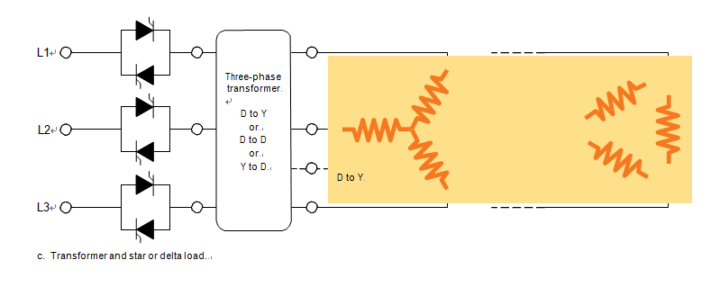
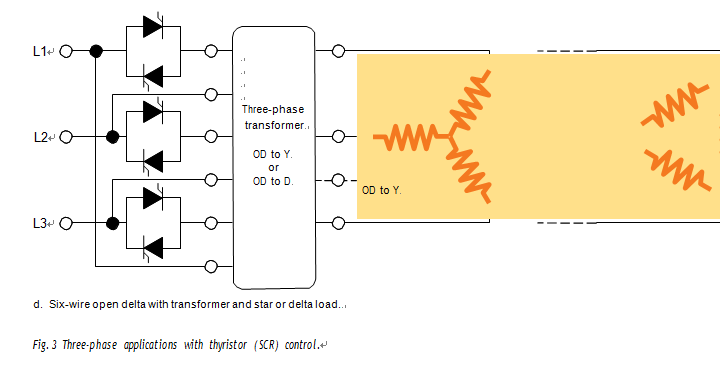
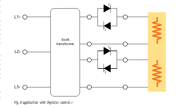
Fig. 2 and 3 on pages 3 – 4 show applications with thy- ristor control.

on/off Control
tapped transformer
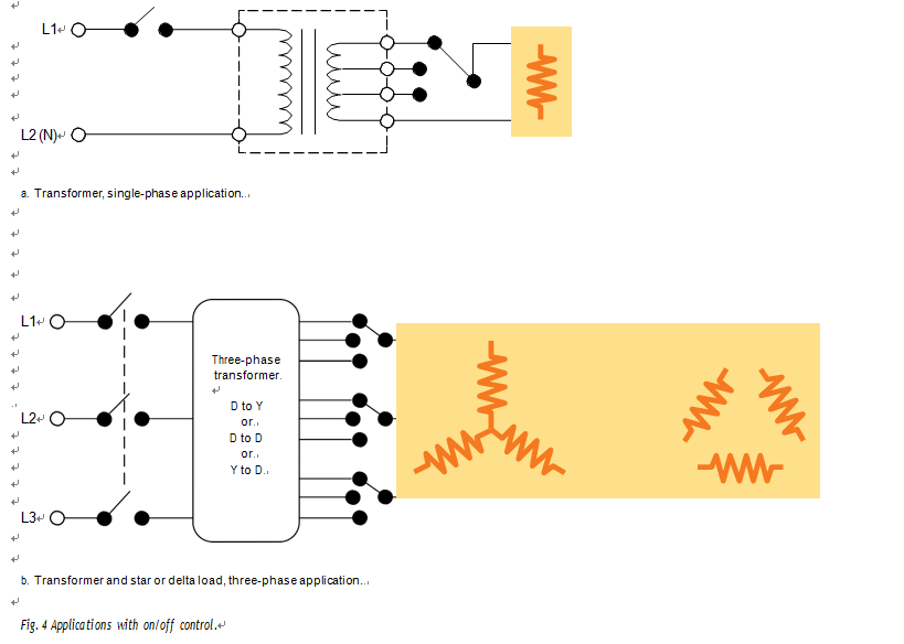
Controlling a furnace with QS MoSi2 elements by a contactor regulated on/off system and a tapped transformer has some disadvantages compared to thyris- tor control. The main disadvantages are longer on/off periods, which results in less accuracy in temperature control and non-synchronized switching, which means that it creates more transients. There is also mechanical wear on the contactor.
Transformers for stepless voltage regulation are some- times used to provide accurate control of the energy input in line with the actual requirement.
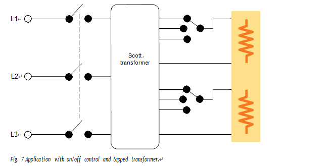
Fig. 4 below, shows applications with on/off control and tapped transformer.
Contactor switch, changing the element connection
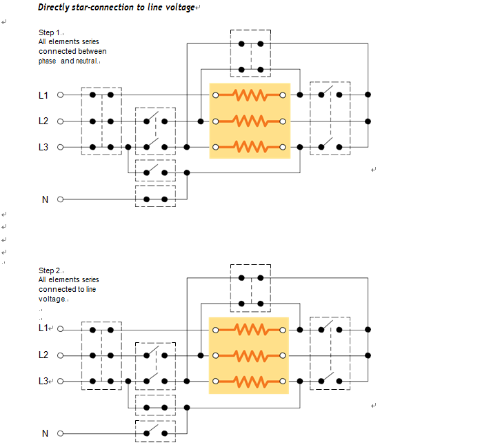
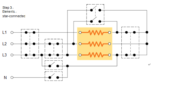
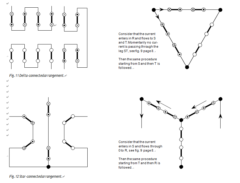
Fig. 5 on page 6 shows a wiring diagram with the elements star-connected to line voltage. By series- connecting all elements between one phase and neutral, the starting voltage is reduced to 33% of full operating voltage. The intermediate step is to connect the elements in series between two phases, which corresponds to 58% of operating voltage. Finally, the elements are switched to star connection.
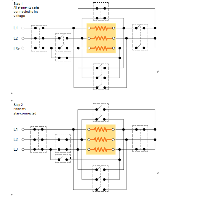
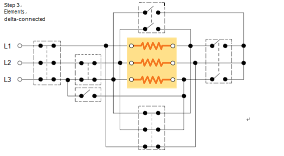
Fig. 6 on page 6 shows a wiring diagram with the elements delta-connected to line voltage. By series- connecting all elements between two phases, the starting voltage is reduced to 33% of full operating voltage.
The intermediate step is to connect the elements in star, which corresponds to 58% of operating voltage. Finally, the elements are switched to delta connection.
At start-up, all elements can also be series-connected between one phase and neutral and the starting voltage is reduced to 19% of full operating voltage
Scott-connected transformers
When the number of elements is such that a symmetrical three-phase load on the secondary side of the trans- former is not possible e.g. 4, 8, 10, 14 etc. and yet prefer a symmetrical three-phase load on the primary side a scott-connected transformer should be used.
When the load is equal on the two secondary windings, the primary side will be symmetrically loaded. The two secondary phases are electrically displaced by 90°.
Note:
Scott-connections with thyristor control require particu- lar attention for successful operation. Consult Sandvik for advice.
Calculation of transformers
thyristor control
When a transformer is used in combination with thyris- tor control, it must be designed for working with thyris- tors. The main difference is that larger iron cores are needed than when using on-off control. The reason for this is to obtain a lower magnetic flux density through the core.
Typical values of flux density are for:
On/off controlled transformers: 1.6 T (Tesla) Transformer with phase-angle fired thyristors: < 1.4 T
Transformers for on/off control can be used for phase- angle firing to 80% of their power rating.
The rating of the transformer for thyristor control is calculated in the following way:
1.The furnace power needed is determined.
2.The size of thyristor is decided.
3.The size of transformer is based on the maximum power that the thyristor needs to control. Generally the transformer is rated 10 – 20% higher than the furnace power.
on/off control
When a transformer is used in combination with on/off control, it must be designed for the maximum continu- ous loading.
Generally it is accurate enough to calculate the power at full operating element voltage and the maximum current permitted for the actual element dimension. Maximum continuous element current for different element dimen- sions is:
Element size: 3/6 4/9 6/12 9/18 12/24 Current, A 75 115 200 365 560
When heating a furnace from room temperature the starting voltage is normally 1/3 or 1/4 of operating voltage to avoid overloading of the electrical equipment. Transformers provided with steps for 1/3, 2/3, or 1/4, 1/2, 3/4, and full operating voltage is utilized
Wiring to counteract electro magnetic for CES
Current passing through two parallel conductors produces an electromagnetic force between them. If the cur- rent flows in the same direction in the two conductors, there is an attracting force and if it flows in the opposite direction there is a repelling force Hence, in a two-shank QS MoSi2 element, a repel- ling force is set up between the two shanks, which leads to an increase in the distance, a, between the shanks of the heating zone.The result of the repelling force and gravitation on the heating zone of a vertically mounted QS MoSi2 element means that a state of equilibrium tends to be reached.
The degree of deformation depends on the amperage I, the length of the heating zone Le, and the distance between the shanks The diagram shows how to calculate the distances necessary to counteract the effect of electro- magnetic force on QS elements.
The effect of the repelling force is reduced if the distance between the shanks is increased. It has been found from practical experience that to avoid excessive deforma- tion, the minimum value of, a, should not be below the following:
Element size Minimum a Normal a
12/24 50 mm (2 in) 80 mm (3.1 in)
9/18 40 mm (1.5 in) 60 mm (2.4 in)
6/12 25 mm (1 in) 50 mm (2 in)
4/9 20 mm (0.8 in) 25 mm (1 in)
3/6 20 mm (0.8 in) 25 mm (1 in)
If two or more elements are installed together, it is important that they are connected in such a way that the current flows in the opposite direction in two adjacent shanks that are placed close together.
all the repelling effects are of the same magnitude, they balance each other and do not increase the distance between the element shanks. Normally, the distance between adjacent elements is greater than, a, and conse- quently the repelling effect between the two shanks of an element will dominate. The result is an increase .
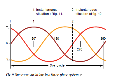
In the case of element groups connected to a three-phase supply, the connecting points should be combined in such a way that the currents in the adjacent shanks of two Kanthal® Super elements have a phase displacement of 120°. Regardless of the phase displacement, it is always a repelling force which occurs between the two shanks of a QS element, and which varies between zero and maximum, see fig. .
In fig. “Correct” below, the electromagnetic force between shank “B” (through which a current “ I1” flows) and shank “C” (through which a current “ I2” flows) produces a repelling effect due to the angular displace- ment between the two phases to which the elements are connected
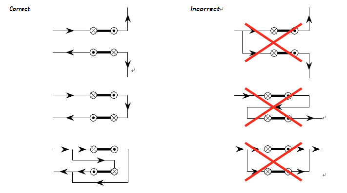
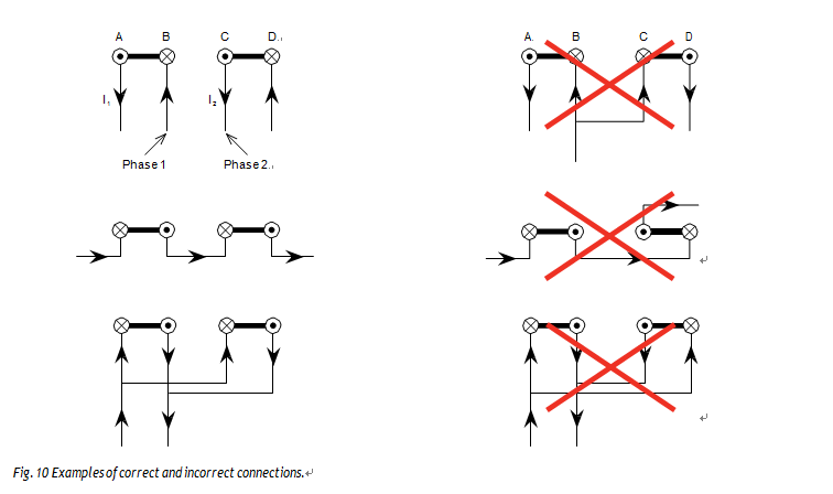
In three-phase systems the connecting points should be combined in such a way that the currents in the adjacent shanks of two QS Super elements have a phase displacement of 120°. Any other connection should be avoided, since the magnetic force will then have a predominantly attracting effect. This intensifies the effect of the repelling forces acting on the two elements, which can lead to severe deformation.
In order to facilitate the correct connection of QS MoSi2 elements to a three-phase supply, bearing in mind that the phases are 120° apart, the current flow direc- tions should be regarded as in fig. 1and 2 below, as follows:
1.The current in two phases flow in opposite directions During part of the cycle the currents will flow in the same direction. The maximum attracting effect is obtained when the currents have half the value of the momentary maximum current. The average action, however, is repelling.
2.Two currents from the neutral point flow in opposite directions
The same as under 1. above.
3.Two currents which come from a common phase connect- ing point flow in the same direction
Remember that two currents from a common phase connec- tion always flow in the same direction. Adjacent elements must never be connected in parallel to the same phase
MAINTENANCE
FACTORS THAT AFFECT MoSi2 ELEMENT LIFE
MoSi2 elements do not exhibit any change in resistance when they are used continuously in air. While a Silicon Carbide heating element will increase in resistance (age) with use, the resistance of a MoSi2 heating element will not change at all. Therefore, in theory, a MoSi2 heating element should last for many years.
However, in reality, there are a number of other factors that usually cause MoSi2 elements to fail, which makes it nearly impossible to predict element life, even under the ideal conditions. Some of the more common modes of failure for MoSi2 elements include:
• Pest – oxidation/degradation of the cold ends – happens if the ends get too hot.
• Electric contact failure – i.e. arcing due to loose straps
• Erosion and Spalling – the protective glaze layer can flake away when cycling the temperature, eventually eroding the element after many cycles.
• Mechanical Forces – hot elements soften and can distort depending how they are oriented in a furnace.
• Insulation Issues – elements too tight in insulation, insulation shifts and breaks the element, or elements contact the insulation and overheat.
• Product contamination – product or atmosphere reacts with the protective glaze causing deterioration of the element.
• Overheat / Control failures
• Over power – too high a watt loading
Unfortunately there is no way to predict the life of a MoSi2 element in an application because one can not predict how any of the above factors will come into play. Generally, the higher the temperature, the more likely one of the above problems will occur. We have a test element that has been operating at 1400ºC in air with no product load for more than 4.5 years now with no sign of changing. It is doubtful that the same element would last that long at 1775ºC. We would expect problems due to spalling or distortion to shorten the life.
The MoSi2 element are manufactured to the same resistance value as the competitors brand therefore they are interchangeable. We offer very fast delivery and excellent customer service.
Troubleshooting
QS MoSi2 element is a long lasting heating element due to its low ageing rate. Installed according to our recommenda- tions, their life is to most operator´s satisfaction.
Element life is limited due to several reasons, but the major reason for failure is rarely due to material faults or workmanship.
The design of the element lead through is critical for optimum element life.
The most common reasons for element failure, which we have seen have been due to:
Careless handling
•Handling of element packages by the carriers whilst in transit.
•Handling of elements by the customer after being removed from the package.
Mechanical damage
•Breakage of elements after being installed in the fur- nace e.g. bumping into an element with a wrench or elbow when carrying out repair work inside a furnace. Also, breakages when elements are removed before relining a furnace.
Mechanical stress
All roof suspended elements should be hung freely to allow unrestricted movement of the element shanks during expansion and contraction due to electromag- netic forces and thermal expansion.
Any binding-sticking of the elements during thermal cycling can result in mechanical and thermal stresses. If this is the case, the element will typically break around the fusion welded joint between the heating zone and terminals.
The contact straps should be long enough so that no stresses are transferred to the elements. If there is suf- ficient space available, it is preferable to use busbars or terminal posts for series connecting elements as the risk of damaging adjacent elements will be reduced when replacing individual elements.
Chemical attack
Compounds and gases, which may have a detrimental effect on QS MoSi2 material .
Overheated elements
When the element temperature exceeds the limit for each of the three qualities, the silica in the material starts to boil. The MoSi2 depletes through evaporation of the silica and the hot zone shows signs of surface cracking and is pitted in appearance. The effect is the same if part of the hot zone is restricted to radiate freely. If one side of the hot zone is too close either to the furnace wall or some other restriction, this side can show signs of overheating.
Overheated contacts
Either one or a combination of the following items can cause too high a temperature on the contacts:
•Chimney effect.
•Terminal length protruding outside the furnace being too short.
•Contacts become loose.
•Poor roof insulation (insufficient thickness, quality, cracking or degradation).
•Poor ventilation over the contacts.
Chimney effect
The terminals should be sealed at the cold face with ce- ramic fiber to prevent convective and radiant heat losses (elements must still be able to move freely).
Terminal length too short
It is quite common to see installations where the con- tacts are very close to the holders.
Loose contacts Can cause thermal shock breakages due to sparking between contact and terminal end. Symptoms: partly melted contacts, thermal cracking of terminal end due to arcing.
When low temperature oxidation (pest) occurs under- neath the aluminizing, the temperature has been far too high. The effect is the same as with loose contacts.
CHECKLIST OF INFORMATION REQUIRED TO TROUBLESHOOT MoSi2 HEATING ELEMENT PROBLEMS
1.Customer data
Customer Name:
Contact:
Contact Name:
Contact email:
Address:
Contact phone:
Products manufactured/Industry:
2.Furnace data
Furnace builder:
Furnace type:
Production capacity, lb/h:
Production Process:
Furnace Power Rating, kW:
Furnace Temperature, °C or °F Firing Cycle:
Number of Zones Time to temperature:
Refractory/Insulation thickness Refractory Insulation Composition:____________ Diameters of holes in refractory:
Ceramic Terminal Tube used, size:____________ Width Height Length Chamber/Zone dimension:
Furnace atmosphere:
Is atmosphere What is the atmosphere dew point?
contained in muffle:
3. Electrical data:
Electrical orientation (Wye/Delta/Single-Phase):______________
SCR Rating:
Transformer Voltage taps: ______________________
SCR Manufacturer:
Transformer Rating: ______________________
Method of Control (SCR, Transformer Manufacturer: ______________________
SSR or Contactor):
If SCR, what firing method is employed?(phase-angle, fast cycle with phase-angle start, etc? time base, if known):__________________________________________________________
RMS Current limit setting:
Volt (AC) Phase Hz Main Line Power __________________ __________________ ___________________
volatiles are given off from the load during heating? Is there any steam?
4.Element data
Type of element & part number: ______________________
Number of elements ___________________
Element loading: ______________________
Power per element, kW:_____________________
Element temperature: ______________________
Hot Zone (Le) Length ___________________
Element dimension: ______________________
Cold End (Lu) Length: ___________________
Element Spacing (Centerline to Centerline)________________
Element spacing from chamber walls:__________
5.Installation question
Type of element holders used:
Bent terminals?:
Sealed terminal lead throughs?:
Air cooled lead throughs?
How are the elements supported?
(where applicable): Are passage plugs/ terminal tubes/ lead-in bricks being used?
Are the terminal holes parallel with each other or made in some other way?
Are the terminal holes free of debris?
(any signs of condensates in the holes?) If yes, do you know/what do you think the residues are?
Are the element terminals being packed around with fiber at the ends where they pass through the refractories?
Are the elements still able to move freely in both linear and radial directions? (important for thermal expansion/contraction) Is there sufficient slack in the length of the aluminum straps so as to not transfer stress to the elements?
Are the element tapers all within the heating chamber and not back inside the insulation?
Are all elements operating in the same environment?
(usually yes, but if some elements are in a gas stream, while others are not, then the conditions between one element and another may be different. If no, please expain) What orientation are the elements installed in?
(Normally vertical but can be horizontal resting on tile/supports, etc.) Are there any signs of residues on the element hot zones?
Are there any signs of residues on the element cold ends


 martin@qs-heatingelements.com


